3
This section covers the installation of the Encore/ST G4 into Power Mac AGP
Graphics and Gigabit Ethernet models. If you are installing this product into a
Digital Audio model, skip to page 6. If you are installing this product into a
QuickSilver 2001 model, skip to page 10.
Shut Down and Open Computer
1. Shut down your Power Mac. If the computer has been on, allow 20 minutes
for it to completely cool before beginning the installation.
2. If you need to move the computer to a different area where you can work
freely, disconnect any connected cables, move the computer, then reconnect
the power cord.
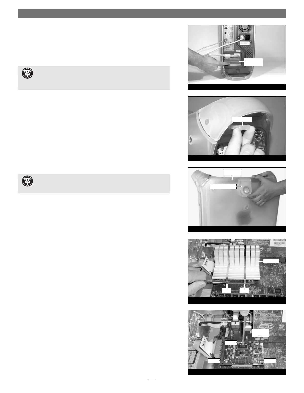
3. Touch a port access cover on the back of the computer (Figure 4) to dis-
charge any potentially damaging static electricity.
4. Disconnect the power cord from the computer.
5. Locate the security lock at the back of the computer (Figure 5). If it is not
already pressed in, do so now.
6. With the right side of the case facing you, open your Power Mac by lifting
the release latch and lowering the side panel away from the computer’s case
(Figure 6).
Remove Heat Sink
Locate the processor heat sink on the logic board (Figure 7); your heat sink may
appear different from what is pictured. Using caution to avoid touching the
processor card, grasp one of the clips securing the heat sink with needle-nose
pliers, between the heat sink and processor card. Pull down and away to unhook
one side of the clip from the processor card (Figure 6). Push the clip away from
you to unhook it from the other side. Repeat these steps with the other clip. Once
the clips have been unhooked, gently lift the heat sink and clips away from the
processor and set them aside, but not on the logic board.
Remove Processor Card
Remove the three screws securing the processor card to the logic board (Figure 8).
Grasping the processor card by its edges, carefully lift it straight up and away from
the logic board.
Installation—AGP Graphics and Gigabit Ethernet Models
Figure 7
Figure 8
clip clip
processor
card
heat sink
screw
screw
screw
Figure 6
raise release latch
side panel
Figure 5
security lock
Figure 4
port access
cover
Support Note: When handling computer products, take care to prevent
components from being damaged by static electricity; avoid working in
carpeted areas. Handle processor upgrade cards only by their edges and avoid
touching connector traces and component pins.
Support Note: To avoid generating a static charge in your body, do not
walk around the room until after you finish installing the Encore/ST card
and close the computer.
 Loading...