Names and Functions of Parts / Connections
7
Names and Functions of Parts
The rear panel of the AWS-G500 is the only part that differs from the
AWS-G500E. For details on the other parts, refer to the AWS-G500E Operating
Instructions.
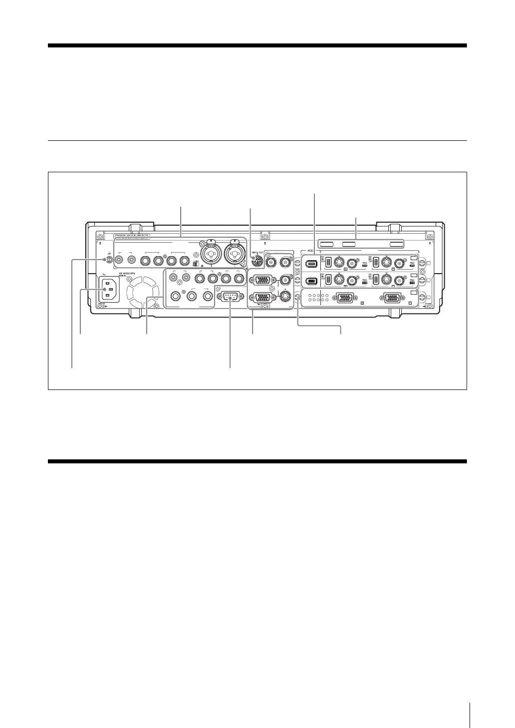
Rear Panel
For details on the function of each part on the rear panel, refer to the
AWS-G500E Operating Instructions.
Connections
The following figure shows a sample system configuration and signal flow. For
details on how to make the connections, refer to the AWS-G500E Operating
Instructions.
After connecting each device, you must configure settings on the unit for each
input and output signal.
For details on settings for each input and output signal, refer to the AWS-G500E
Operating Instructions.
AC IN
LINE MIC/LINE
MIX
HEADPHONES
MONI INTERCOM
15
69
RGB PGM
S VIDEO
AUX PGM RGB
COMPOSITE
MIC/LINE
PUSH PUSH
AUDIO IN
VIDEO IN
AUDIO OUT VIOEO OUT
87 65 4 3
RRLL
RL
21
21
OFF
ON
1
2
3
RGB RGB
I.LINK
S VIDEO
COMPOSITE
S VIDEO
COMPOSITE
S400
OFF
ON
OFF
ON
I.LINK
S VIDEO
COMPOSITE
S VIDEO
COMPOSITE
S400
OFF
ON
OFF
ON
4 Power supply
connector
(~AC IN)
1 Audio inputs
1
VISCA
connector
7 SD video interface module
3 Video outputs
3 Intercom interface connector
2 Audio outputs
2
Cable clips
5 Ground terminal
8 PC video interface module
 Loading...