....
I
-..J
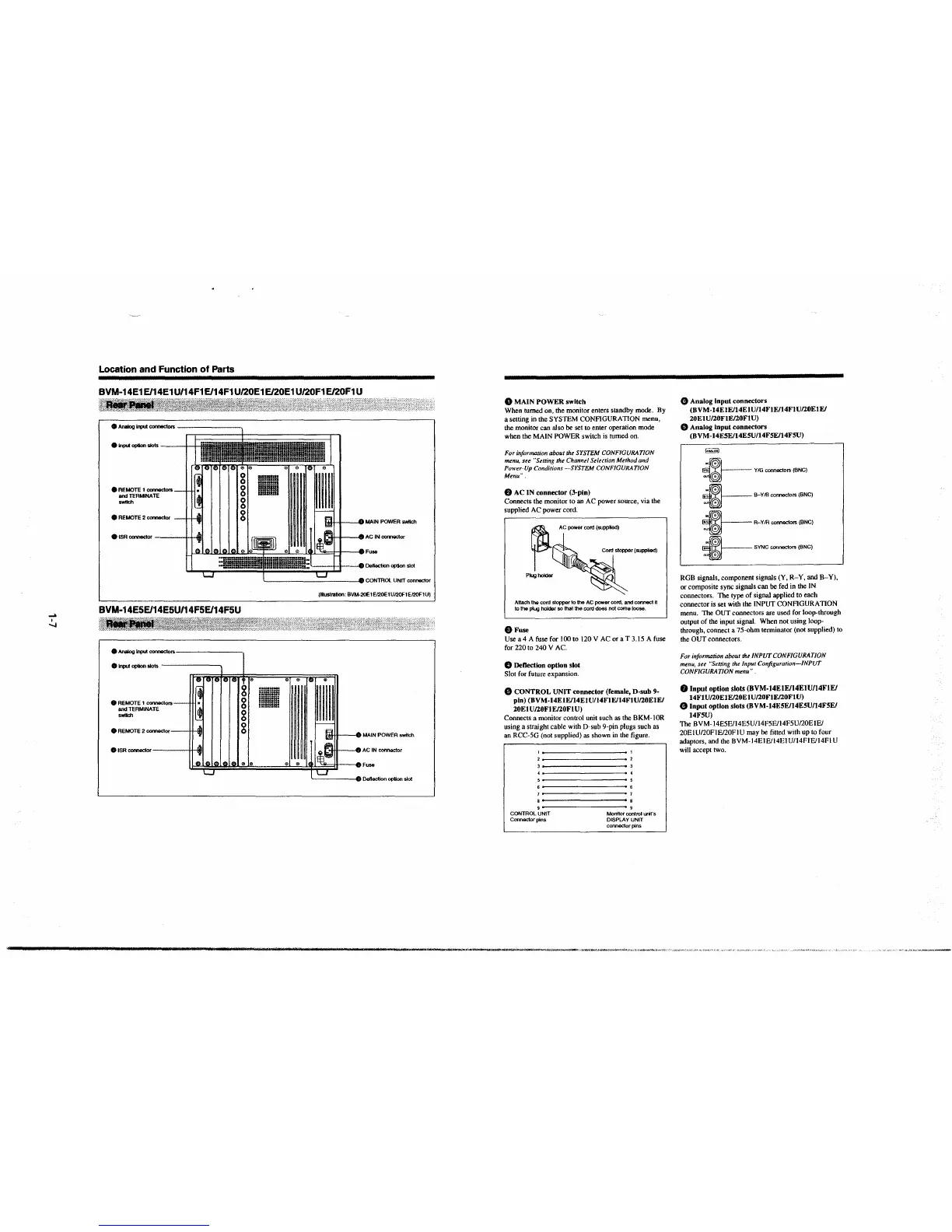
Location and Function of Parts
BVM-14E1E/14E1U/14F1E/14F1U/20E1E/20E1U/20F1E/20F1U
• Analog input comecton;
e 1npu1 option - ---+-+-
iol I I O MAIN POWER switch
• lSR connector -·- 01 I 8 AC IN connecto,
H 0lf>lf>I~ @I ® l~I¾ H 8Fuse
. i --··· ·--~:
I j ............. ,H ........... H.-......... ,;,-·r·---• Deflection option siot
BVM-14E5E/14E5U/14FSE/14FSU
• Analog Input comecton;------~
e 1npu1 option s1o1s -------.
8 REMOTE 1 COM8Ctors ----
and TERMINATE
switch
• REMOTE
2 connector
0 ISR connecto, 11 filll
~----------• CONTROL UNIT connector
(IUuslrabon: BVM-20E1El20E1U/20F1El20F1U)
®
lil+f--eMAINPOWEA switch
AC IN connector
Fuse
'-----48DDeflectlon option slot
0 MAIN POWER switch
When turned on, the monitor enters standby mode. By
a setting in the SYSTEM CONFIGURATION menu,
the monitor can also
be set to enter operation mode
when the MAIN POWER switch is turned on.
For information about the SYSTEM CONFIGURATION
menu, see "Setting the Channel Selection Method and
Power-Up Conditions ~SYSTEM CONFIGURATION
Menu".
8 AC IN connector (3-pin)
Connects the monitor to an AC power source, via the
supplied AC power cord .
~~-~--
?~-,~
Attach the cord slopper to the AC power cord, and connect it
to the plug header so that the cord does not come loose,
8Fuse
Use a 4 A fuse for JOO to 120 V AC or a T 3.15 A fuse
for 220 to 240 V AC.
e Deftection option slot
Slot for future expansion.
8 CONTROL UNIT connector (female, D-sub 9·
pin) (BVM-14EIE/14EJU/14FtE/14FJU/20ElE/
20EIU/20FlE/20FIU)
Connects a monitor control unit such as the BKM-IOR
using a straight cable with D-sub 9-pin plugs such as
an
RCC-5G (not supplied) as shown in the figure.
,----------
' 9
CONTROL UNIT Monitor control unit's
Connector pins DISPLAY UNIT
connector pins
----~~·,..,-t__,v,4;...,,,,.,..~,,,,-c."_......_.,_,_,.,
G Analog Input connectors
(BVM-14EIE/14ElU/I4FtE/14FlU/20EIE/
20EIU/20F1E/20FIU)
0 Analog input connectors
(BVM-14ESE/14ESU/14FSEl14FSU)
~
:.~L
~
---·- Y/G connectors (BNC)
1§11 9-YIB connectors (BNC)
1--
.
._
R-Y/A connectors (BNC)
.
t}--
SYNC connectors (BNC)
.
RGB signals, component signals (Y, R-Y, and B-Y),
or composite sync signals can be fed in the IN
connectors. The type of signal applied to each
connector is set with the INPUT CONFIGURATION
menu.
The OUT connectors are used for loop-through
output of the input signal. When not using
Ioop-
through, connect a 75-ohm terminator (not supplied) to
the OUT connectors.
For information about the INPUT CONFIGURATION
menu, see "Setting the Input Configuration-INPUT
CONFIGURATION menu".
8 Input option slots (BVM-14ElE/14EIU/14FIE/
14Fl U/20El E/20El U/20FIE/20Fl U)
G Input option slots (BVM-14E5E/I4ESU/14FSE/
14F5U)
The BVM-14E5E/i4E5U/14F5E/14F5U/20EIE/
20EIU/20FJE/20FIU may be fitted with up to four
adaptors, and the BVM-14EIE/14EIU/14FIE/14FI U
will accept two.