_,.
I
(X)
Location and l!!'unctlon of Parts
8 REMOTE 1 connectors (female, D-sub 9-pin),
and TERMINATE switch
(BVM-14ElEJ14ElU/14FlE/14FlU/20ElE/
20ElU/20FlE/20FlU)
8 REMOTE 1 connectors (female, D-sub 9-pin),
and TERMINATE switch
(BVM-14ESEl14E5U/l4F5EJ14F5U)
REMOTE 1
"' 11:1111, REMOTE 1 IN connector
a, I TERMINATE switch
11'.illl-' REMOTE 1 OUT coonector
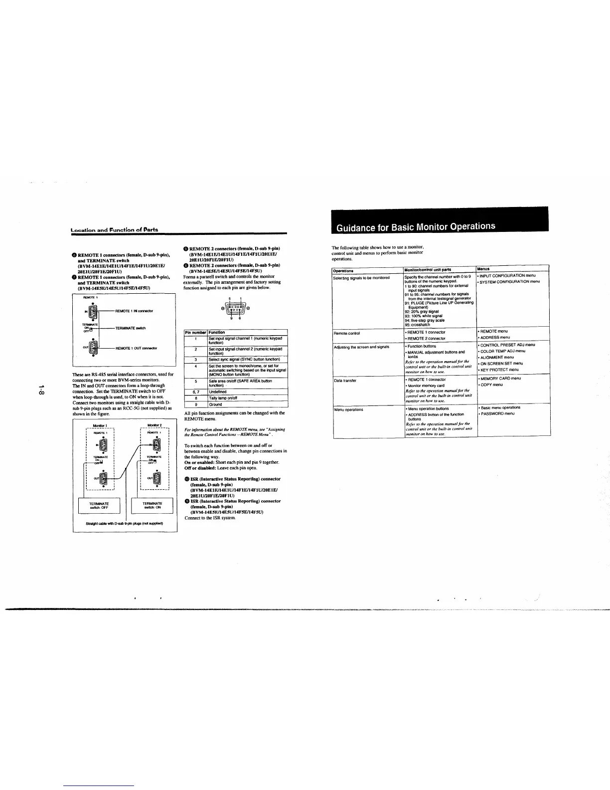
These are RS-485 serial interface connectors, used for
connecting two or more BVM-series monitors.
The IN and OUT connectors form a loop-through
connection. Set the TERMINATE switch to OFF
when loop-through is used, to ON when it is not.
Connect two monitors using a straight cable with D-
sub 9-pin plugs such as an RCC-SG (not supplied) as
shown in the figure.
Moritor1
I --- -- I
: REMOTE 1 :
: o· :
I •o I
I N :• I
I •• I
I I
' . '
: TERMINATE :
I ONn :
I
I
:
ourlll.:IL.J..__./
TERMINATE
switch: OFF
Monlt0f2
: fU:MOTE 1 l
I
~
:
'
I
I
I
I
i
'
'
OOT~ i
Ql
9 I
L---------- I
TERMINATE
swllch:ON
Straight cable - D-sw 9-pln plugs (not supplied)
Ci) REMOTE 2 connectors (female, D-sub 9-pin)
(BVM-14ElE/14ElU/14FlE/14FlU/20ElE/
20El U/20FlE/20Fl U)
8 REMOTE 2 connectors (female, D-sub 9-pin)
(BVM-14E5E/14E5U/14F5E/14F5U)
Forms a pararell switch and controls the monitor
externally. The pin arrangement-and factory setting
function assigned to each pin are given below.
5 1
®O®
9 6
Pin number
Function
1
Set input' signal channel 1 (numeric keypad
function)
2
Set input signal channel 2 (numeric keypad
function)
3
Select sync signal (SYNC button function)
4
Set the screen to monochrome, or set for
automatic switching based on the input
signal
(MONO button function)
5
Safe area on/off (SAFE AREA button
function)
6, 7
Undefined
8
Tally lamp on/off
9
Ground
All pin function assignments can be changed with the
REMOTE menu.
For information about the REMOTE menu, see "Assigning
the Remote Control Functions
-REMOTE Menu".
To switch each func:tion between on and off or
between enable and disable, change pin connections in
the following way.
On or enabled: Short each pin and pin 9 together.
Off or disabled: Leave each pin open.
$ ISR (Interactive Status Reporting) connector
(female, D-sub 9-pin)
(BVM-14E1E/14ElU/14FtEJ14FlU/20ElE/
20ElU/20FlE/20FlU)
4!) ISR (Interactive Status Reporting) connector
(remale, D-sub 9-pin)
(BV
M-14ESE/14ESU/14F5E/14F5U)
Connect to the JSR system.
Guidance for Basic Monitor Operations
The following table shows how to use a monitor,
control unit and menus to perform basic monitor
operations.
Operations
Monitor/control unit parts
Selecting signals to
be monitored
Specify the channel number with O to 9
buttons of the numeric keypad.
1 to 90: channel numbers for external
input
signals
91 to 95: channel numbers for signals
from the internal testsignal generator
91: PLUGE (Picture line UP Generating
Equipment)
92: 20% gray signal
93: 100% white
signal
94: five-step gray scale
95: crosshatch
Remote control
• REMOTE 1 connector
• REMOTE 2 connector
Adjusting the screen and signals
• Function buttons
• MANUAL adjustment buttons and
konbs
Refer lo the operation manual ft>r the
control unit or the built·in control unit
monitor on
how to use.
Data transfer
• REMOTE 1 connector
• Monitor memory card
Refer to the operation manual for the
rnntrol unit or the built-in t·ontrol unit
numitor on how to use.
Menu operations
• Menu operation buttons
• ADDRESS button of the function
buttons
Refer to thr operation manual for the
control
unit or the built-in control unit
monitor on how to use.
Menus
• INPUT CONFIGURATION menu
• SYSTEM CONFIGURATION menu
• REMOTE menu
• ADDRESS menu
• CONTROL PRESET
ADJ menu
• COLOR TEMP
ADJ menu
• ALIGNMENT menu
• ON SCREEN SET menu
• KEY PROTECT menu
• MEMORY CARD menu
•COPY menu
• Basic menu operations
• PASSWORD menu
 Loading...


