...
I
w
-..J
• BKM·32H
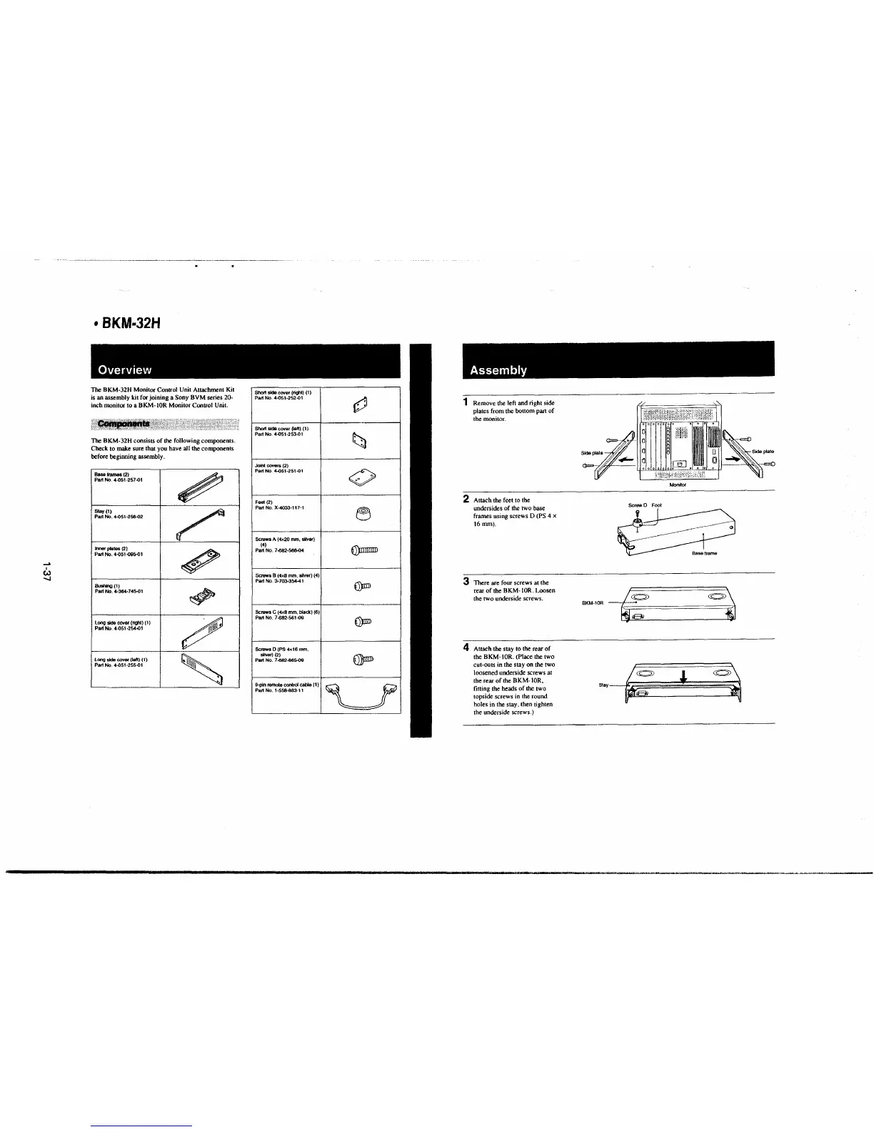
Overview
The BKM-32H Monitor Control Unit Attachment Kit
is an assembly kit for joining a Sony BVM series 20-
inch monitor to a BKM-IOR Monitor Control Unit.
The BKM-32H consists of the following components.
Check to make sure that you have all the components
before beginning assembly .
Base frames (2)
Part No. 4--051-257-01
Stay(!)
Part No. 4-051-256-02
lmor plates (2)
Part No. 4-051-09S-01
Bushing (1)
Pait No. 4.354.745-01
Long side cover (ligh1) (1)
Pa~ No. 4-051-254-01
Long skte cover (iefl) (1)
Part No. 4-051-255-01
~
~
~
~
~
Short side cover (right) (1)
Part No. 4-051-252-01
Short sidecover(lefl) (1)
Part No. 4-051-253-0t
Joint COY81'& (2)
Part No. 4-051-251-0t
Fool (2)
Part No. X-4033-117-1
Screws
A (4x20 mm. silver)
(4)
Part No. 7-682-566-04
Screws 8 (4x8 mm, silver) (4)
Part No. 3-7()3..354-41
Screws
C (4x8 mm. black) (6)
Part No. 7-682-561-09
Screws
D (PS 4x16 mm,
sHVor) (2)
Part No. 7.s82-665-09
9-pln Almoto central cable (1)
PartNo.1-558,-883-.11
~
t;;i
.
0
0
~
€))IlmrrD
~
~
€I)mn
~
Assembly
1 Remove the left and right side
plates from the bottom part of
the monitor.
2 Attach the feet to the
undersides of the two base
frames using screws D (PS 4 x
16mm).
3 There are four screws at the
rear of the BKM-IOR. Loosen
the two underside screws.
4 Attach the stay to the rear of
the BKM-IOR. (Place the two
cut-outs
in the stay on the two
loosened underside screws at
the rear of the BKM- IOR,
fitting the heads of the two
topside screws in the round
holes in the stay, then tighten
the underside screws.)
~I
~
a
Side pl Q
- '' ,:)¾\;(:,,::;fc'; .. .,
I l I~·-=
o/ o /o o
Screw D Foot
BKM-lOR
~
~
Sray~
Monitor
~
l
~
 Loading...


