9Location and Function of Parts
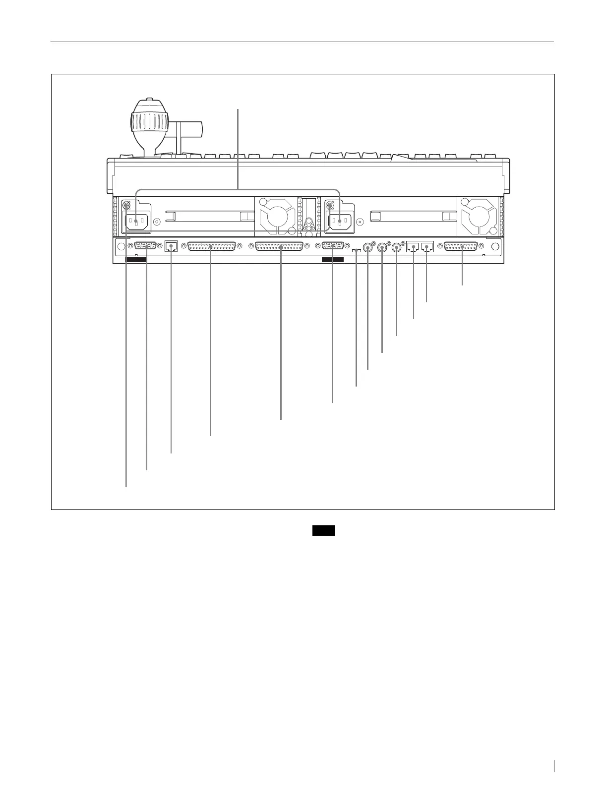
MKS-9011A/9012A Rear Panel
a - AC IN (AC power input) A and B connectors
(3-pin)
Connect to 100 to 240 V AC power supply with the
optional AC power cords.
b GPI (General Purpose Interface) connector
(D-sub 25-pin)
Connect to external devices for input and output of trigger
signals. Up to eight inputs and eight outputs are possible,
with input and output conditions set on the center control
panel.
c PERIPH (peripheral) connector (RJ-45)
Connect to the DCU-8000 Device Control Unit Pack with
a cross cable to enable communications with the DCU-
8000.
Note
An Ethernet switch is required to connect two or more
DCU-8000 Device Control Units.
d CTRL (control) connector (RJ-45)
Connect to an Ethernet switch
*
.
The MVS-8000A/DVS-9000 Switcher Processor Pack, the
MVE-8000A DME Processor Pack and other devices are
connected in the same way to the Ethernet switch to form
a network for exchange of signals between the devices.
This network is used primarily to control the various
devices from the center control panel.
* For information about Ethernet switches that can be used in an MVS
system, contact your Sony service representative.
* Ethernet is a trademark of XEROX Corporation.
For more information about Ethernet switch connectors,
see “MVS-8000A System Configuration” (page 12).
CTRL PERIPH
EXT DISPLAY
EDITOR PANELDATA
POWER A
POWER B
GPIMENU PANEL EXT PANEL
REF IN LTC IN REMOTE
5REMOTE connector
7REF IN connector
2GPI connector
1 - AC IN A and B connectors
9EDITOR PANEL connector
3PERIPH connector
qsDATA connector
4CTRL connector
qaMENU PANEL connector
qdEXT DISPLAY connector
0EXT PANEL connector
6LTC IN connector
875Ω ON/OFF switch
qfU connector
 Loading...