Do you have a question about the Sony CDP-390 and is the answer not in the manual?
Details player performance metrics like frequency response, S/N ratio, dynamic range, distortion, and channel separation.
Covers output levels, impedance, power requirements, consumption, dimensions, and weight.
Lists accessories provided with the unit, such as power cords and remote controls.
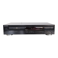
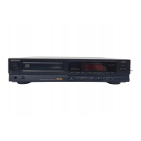
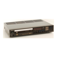
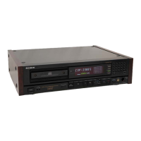
Covers general product details and the location/function of controls.
Summarizes sections on disassembly, adjustments, diagrams, exploded views, and parts lists.
Highlights critical safety components that require specific attention during replacement.
Explains how to measure AC leakage current from metal parts to ground, not exceeding 0.5 mA.
Advises on preventing electrostatic breakdown when handling the optical pick-up block.
Provides instructions for checking laser diode emission safely from a distance.
Details laser diode material, wavelength, output, and safety guidelines during servicing.
Advises against disassembling the pick-up block or adjusting the APC circuit for safety.
Describes the warning label found inside the apparatus regarding invisible laser radiation.
Identifies and describes the function of each button and control on the CD player's front panel.
Lists and describes the functions of buttons on the remote commander.
Details the steps to remove the CD mechanism from the base unit.
Explains how to remove the disc table and the BU-5BD1 base unit component.
Guides on checking RF PLL frequency and RF level/eye pattern using test equipment.
Details focus/tracking gain adjustment and E-F balance check procedures.
Provides steps and waveform examples for adjusting focus gain on the digital board.
Guides on adjusting tracking gain on the digital board with waveform examples.
Shows the complete block diagram of the CDP-190/390, illustrating signal flow and component interaction.
Displays the layout of the main board, line out board, power board, and power switch board.
Provides lead layouts for various semiconductors used in the unit.
Presents the schematic diagrams for the main board and the BD board.
Shows the connections for the optical pick-up block and loading mechanism.
Details the pin names, I/O, and function for IC101 (CXA1372Q).
Illustrates the block diagrams for ICs like TDA1543 and CXD2500.
Shows block diagrams for ICs such as M54641L, LA5601, LA6532, CXD2551M, M5285FP.
Provides an exploded view of the chassis section with a detailed parts list for components.
Presents an exploded view of the CD mechanism (CDM14-5BD1) with parts list.
Shows an exploded view of the optical pick-up block (BU-5BD1) with its component parts.
Lists various types of capacitors with their part numbers, values, and voltage ratings.
Lists various resistors with their part numbers, values, and tolerance.
Lists semiconductors, sockets, and connectors with their part numbers and descriptions.
Lists ICs, transistors, and diodes with their part numbers and types.
Continues the listing of resistors with their part numbers, values, and tolerances.
Lists coils, jacks, motors, and oscillators with their respective part numbers.
Lists remaining resistors, switches, and voltage selection switches.
Details parts related to accessories and packing, such as remote commanders and power cords.
Lists instruction manuals, individual cartons, and cushions.
Corrects the connection procedure for the E-F Balance Check on page 7.
Corrects the block diagram connections on page 9 for IC211 and related components.
Corrects the circuit diagram for muting control involving IC271 and Q271/Q272.
Corrects wiring on the BD board, including IC261 and IC271 connections.
Corrects wiring and component references for the optical pick-up block.
Corrects pin connections for IC261 and IC271 on the BD board.
| Type | CD Player |
|---|---|
| Channels | 2 |
| Frequency Response | 2 Hz - 20 kHz |
| Signal-to-Noise Ratio | 110 dB |
| Channel separation | 100 dB |
| Total Harmonic Distortion | 0.003% |
| Dimensions (W x H x D) | 430 x 100 x 300 mm |
| Disc format | CD |
| Output | 2.0V (fixed) |
| Digital Output | Coaxial |
| Digital converter | 1-bit D/A converter |