— 2 —
CAUTION
Use of controls or adjustments or performance of
procedures other than those specified herein may result in
hazardous radiation exposure.
Notes on chip component replacement
• Never reuse a disconnected chip component.
• Notice that the minus side of a tantalum capacitor may be
damaged by heat.
ATTENTION AU COMPOSANT AYANT RAPPORT
À LA SÉCURITÉ!!
LES COMPOSANTS IDENTIFIÉS PAR UNE MARQUE ! SUR
LES DIAGRAMMES SCHÉMATIQUES ET LA LISTE DES
PIÈCES SONT CRITIQUES POUR LA SÉCURITÉ DE
FONCTIONNEMENT. NE REMPLACER CES COMPOSANTS
QUE PAR DES PIÈCES SONY DONT LES NUMÉROS SONT
DONNÉS DANS CE MANUEL OU DANS LES
SUPPLÉMENTS PUBLIÉS PAR SONY.
SAFETY-RELATED COMPONENT WARNING !!
COMPONENTS IDENTIFIED BY MARK ! OR DOTTED LINE
WITH MARK ! ON THE SCHEMATIC DIAGRAMS AND IN
THE PARTS LIST ARE CRITICAL TO SAFE OPERATION.
REPLACE THESE COMPONENTS WITH SONY PARTS
WHOSE PART NUMBERS APPEAR AS SHOWN IN THIS
MANUAL OR IN SUPPLEMENTS PUBLISHED BY SONY.
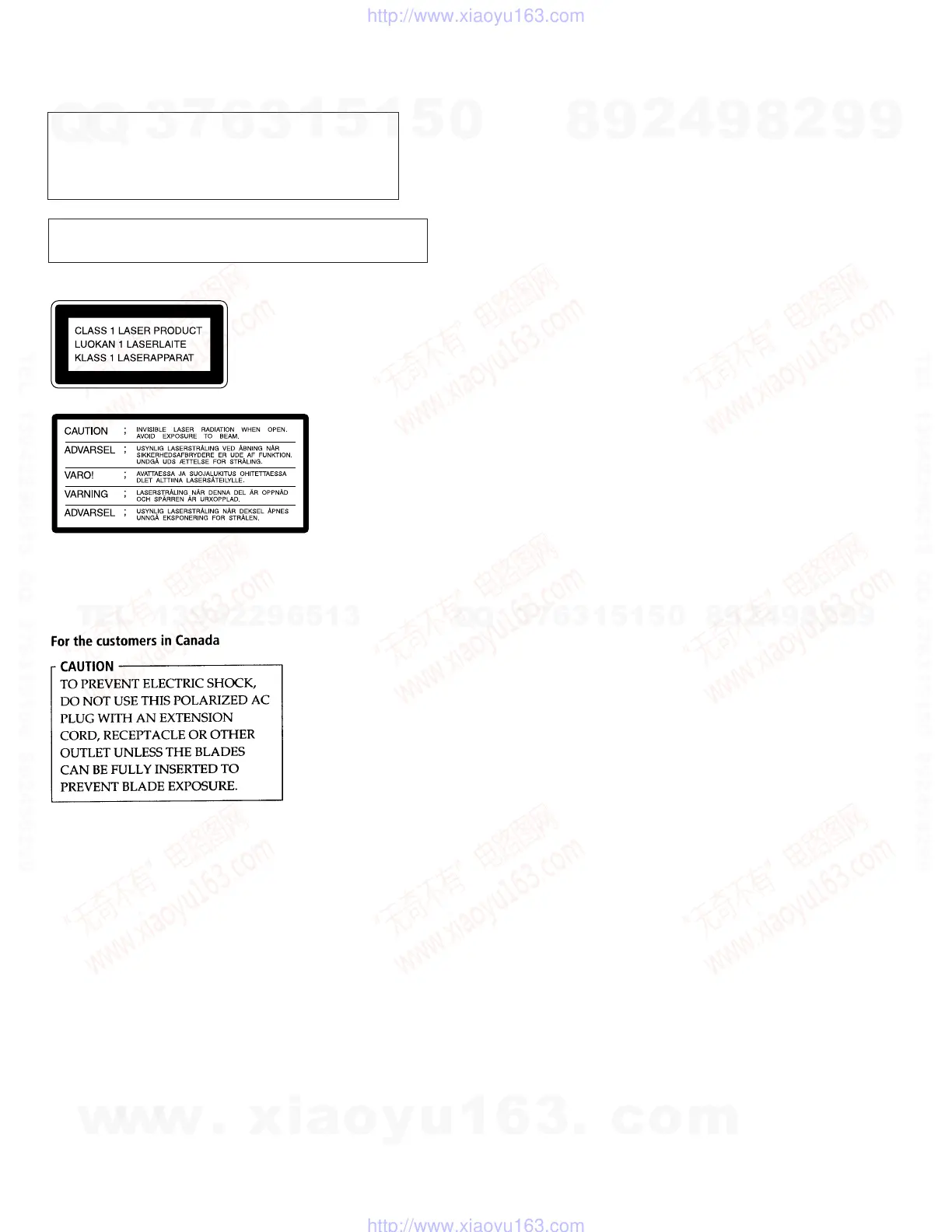
Laser component in this product is capable of emitting radiation
exceeding the limit for Class 1.
This appliance is classified as a
CLASS 1 LASER product.
The CLASS 1 LASER
PRODUCT MARKING is
located on the rear exterior.
This caution label
is located inside
the unit.
TABLE OF CONTEMTS
1. SERVICING NOTE ........................................................... 4
2. GENERAL ............................................................................ 5
3. DISASSEMBLY
3-1. Front Panel Block .................................................................. 6
3-2. CD Mechanism Deck ............................................................. 6
3-3. BU Bracket Assembly ............................................................ 7
3-4. Disc Table .............................................................................. 7
4. TEST MODE ........................................................................ 8
5. ELECTRICAL BLOCK ADJUSTMENTS ................. 9
6. DIAGRAMS
6-1. Circuit Boards Location ...................................................... 11
6-2. Schematic Diagram — BD Section — ................................ 12
6-3. Printed Wiring Board — BD Section —.............................. 15
6-4. Schematic Diagram — Main Section — ............................. 19
6-5. Printed Wiring Board — Main Section —........................... 23
6-6. IC Pin Function
• IC401 System Control, Fluorescent Indicator Tube Drive
(CXP82316-065Q)............................................................ 26
7. EXPLODED VIEWS
7-1. Case and Back Panel Section ............................................... 27
7-2. Front Panel Section .............................................................. 28
7-3. CD Mechanism Section (CDM37-5BD19).......................... 29
7-4. Base Unit Section (BU-5BD19)........................................... 30
8. ELECTRICAL PARTS LIST ......................................... 31
w
w
w
.
x
i
a
o
y
u
1
6
3
.
c
o
m
Q
Q
3
7
6
3
1
5
1
5
0
9
9
2
8
9
4
2
9
8
T
E
L
1
3
9
4
2
2
9
6
5
1
3
9
9
2
8
9
4
2
9
8
0
5
1
5
1
3
6
7
3
Q
Q
TEL 13942296513 QQ 376315150 892498299
TEL 13942296513 QQ 376315150 892498299
http://www.xiaoyu163.com
http://www.xiaoyu163.com
 Loading...