EasyManua.ls Logo

Sony CDP-CE245 Service Manual

Sony CDP-CE245
44 pages
To Next Page IconTo Next Page
Page #1 background imageLoading...
Page #1 background image
SERVICE MANUAL
COMPACT DISC PLAYER
US Model
Canadian Model
CDP-CE245/CE345
AEP Model
UK Model
E Model
CDP-CE345
Australian Model
CDP-CE245/CE345
SPECIFICATIONS
CDP-CE245/CE345
Photo: CDP-CE345 (Silver TYPE)
Model Name Using Similar Mechanism NEW
CD Mechanism Type CDM59-5BD32A
Base Unit Name BU-5BD32A
Optical Pick-up Name KSS-213BA/F-NP

Other manuals for Sony CDP-CE245

Question and Answer IconNeed help?

Do you have a question about the Sony CDP-CE245 and is the answer not in the manual?

Sony CDP-CE245 Specifications

General IconGeneral
TypeCD Player
Frequency Response2 Hz - 20 kHz
Signal-to-Noise Ratio100 dB
OutputAnalog, Digital
Dimensions430 x 300 x 100 mm
Weight3.5 kg
Remote ControlYes
Channels2 (stereo)
Output Voltage2 V
Disc Capacity5 Discs
Digital OutputOptical

Summary

Product Specifications

Laser Specifications

Details on laser type, wavelength, and output power.

Output Specifications

Information on analog and digital output levels and impedance.

Power and General Specifications

Power requirements by region, consumption, dimensions, and weight.

Safety Check-out Procedures

Leakage Test

Procedure to test AC leakage from metal parts to earth ground.

Servicing Notes and Precautions

Handling Optical Pick-up

Guidelines for preventing electrostatic breakdown when handling the optical pick-up.

Laser Diode Emission Check

Instructions for safely checking the laser diode emission.

Disassembly Procedures

Cover Removal

Steps for removing the unit cover.

Front Panel Section

Procedure for disassembling the front panel section.

Mechanism and Main Board Disassembly

CD Mechanism Deck

Steps for disassembling the CD mechanism deck.

Main Board

Procedure for removing the main board.

Base Unit and Table Assy Disassembly

Base Unit

Steps for disassembling the base unit.

Tray and Motor Board Disassembly

Test Mode Operations

Aging Mode Procedures

Mechanism Deck Check Modes

Electrical Checking Procedures

S-Curve Check

Procedure for checking the S-curve waveform.

E-F Balance Check

Procedure for checking the E-F balance of the optical pick-up.

RF Level Check

Procedure for checking the RF signal level.

RF PLL Free-run Frequency Check

Procedure for checking the RF PLL free-run frequency.

Diagrams and Schematics

IC Pin Function Descriptions

BD Board IC101 Pinout

Pin function description for IC101 on the BD board.

Main Board IC Pinout

Display Board IC Pinout

Exploded Views

Front Panel Section Exploded View

Chassis Section Exploded View

CD Mechanism Deck Section-1 Exploded View

CD Mechanism Deck Section-2 Exploded View

Base Unit Section Exploded View

Electrical Parts List

BD Board Parts

List of electrical components for the BD board.
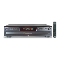
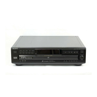
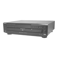
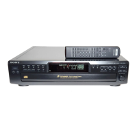
Display and Junction Board Parts

Key, Loading Motor, Main Board Parts

Power SW and Sensor Board Parts

Related product manuals