Do you have a question about the Sony CDP-CE275 and is the answer not in the manual?
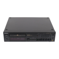
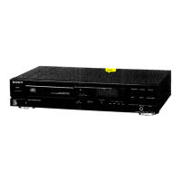
Details on power requirements, consumption, dimensions, and mass of the CD player.
Lists analog and digital output levels, and load impedance for various outputs.
Describes methods for checking AC leakage current from metal parts to ground.
Highlights components critical for safe operation and replacement guidelines.
Covers electrostatic discharge precautions and safe laser beam observation.
Notes on replacing chip components and repairing flexible circuit boards.
Procedures for entering and operating adjustment and key check modes.
Procedures for adjusting and verifying signal levels using an oscilloscope.
| Disc Capacity | 5 Discs |
|---|---|
| Frequency Response | 2 Hz - 20 kHz |
| Signal-to-Noise Ratio | 100 dB |
| Digital Output | Coaxial |
| Channels | 2 |
| Output Level | 2 V |
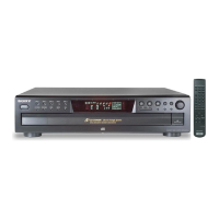
| Type | CD Player |
| Digital-to-Analog Converter | 1 Bit |