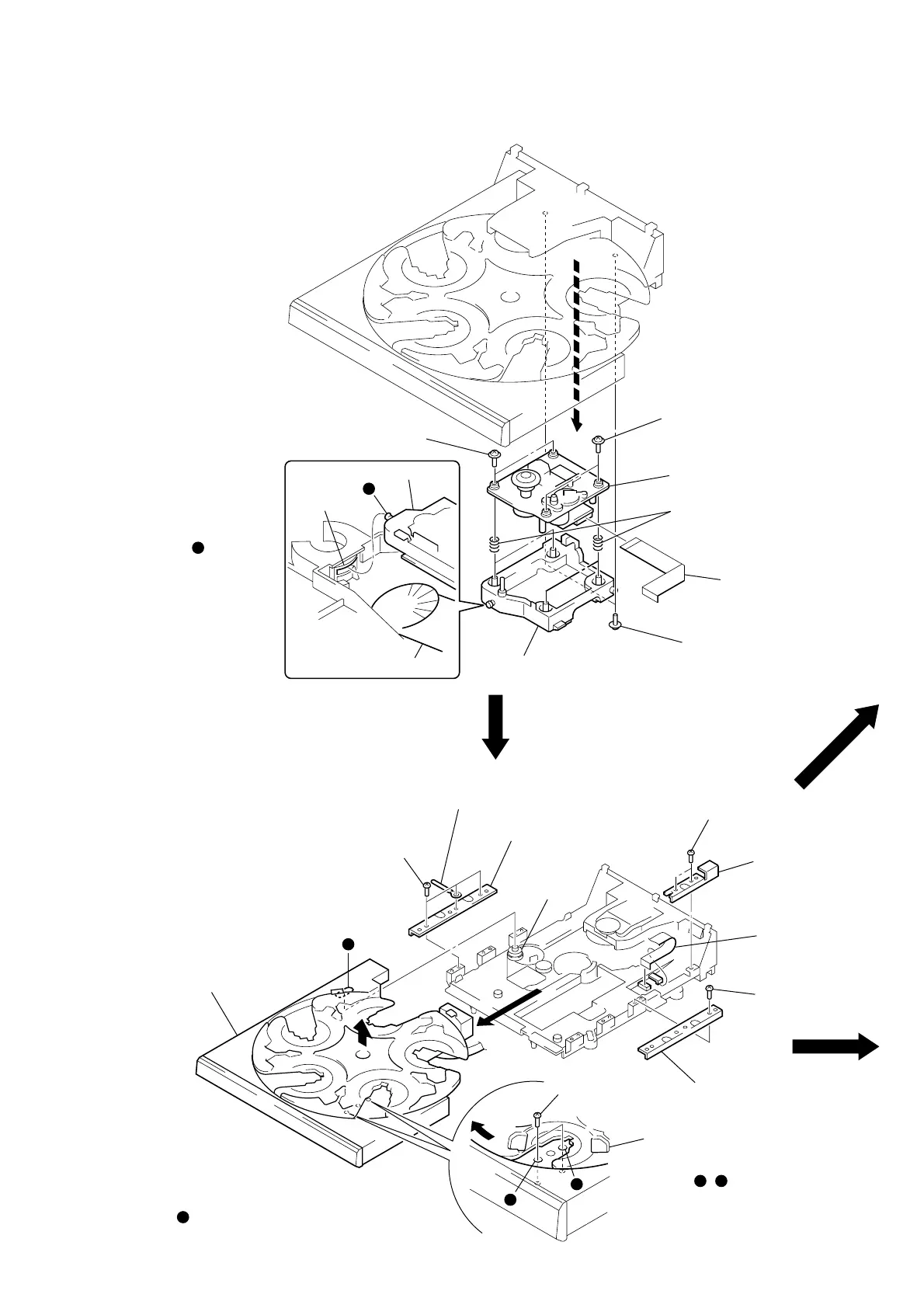
7
BASE UNIT (BU-5BD32A)
4 two screws
(PTPWH M2.6)
4 two screws
(PTPWH M2.6)
5 base unit (BU-5BD32A)
1 wire (flat type) (21 core)
(CN101)
6 four compression springs (932)
3
2 two screws
(PTPWH M2.6)
7 holder (BU) ass’y
lever (lifter)
BU section
Note: When installing the BU
on the chassis, set the
lever (lifter) in free
position, the gear (U/D)
in UP position, and insert
the shaft into the
groove of gear (U/D).
gear (U/D)
b
b
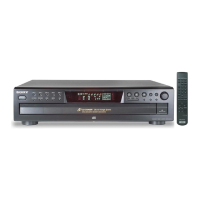
TABLE ASS’Y
Note: When installing the table ass’y
on the chassis ass’y, engage
the gear (loading C) with the groove
by looking into the gear through
a hole in the table ass’y.
qs table ass’y
9 three screws
(BTTP M2.6)
q; clamp
e
c
c
d
d
e
qa bracket (guide)
gear
(loading C)
7 two screws
(BTTP M2.6)
5 screw
(BTTP M2.6)
6 bracket (guide)
2 two screws
(BTTP M2.6)
1 Slide the tray until the screw
that fixes the bracket (guide)
can be seen through a round
hole , in the table ass’y.
3
8 bracket (guide 2)
4 wire (flat type)
(6 core) (CN15)