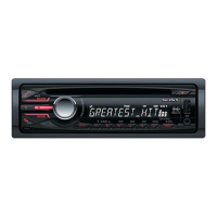
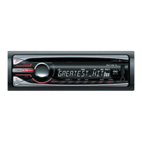
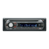
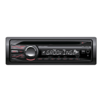
CDX-GT24W/GT240/GT290/GT290S
29
Pin No. Pin Name I/O Description
71 AREASEL 1 I Destination setting pin 1
72 AREASEL 0 I Destination setting pin 0
73 to 80 NCO O Not used. (Open)
81 RE IN1 I Rotary encoder signal input 1
82 RE IN0 I Rotary encoder signal input 0
83 NCO/SA IN I Serial data signal input to electronic volume spectrum analyzer
84 CYRIL SEL I
Cyril correspondence discrimination signal input
“H”: Correspondence, “L”: No correspondence
85 to 88 NCO O Not used. (Open)
89 NCO/SADATD O Serial data signal output to electronic volume spectrum analyzer
90 NCO/SACLK O Serial clock signal output to electronic volume spectrum analyzer
91 KEYACK0 I Key Acknowledge detection signal input (Rotary command signal input)
92 KEYACK1 I Key Acknowledge detection signal input (Front panel signal input)
93 VSM I S meter voltage detection signal input
94 KEYIN1 I Key signal input 1
95 KEYIN0 I Key signal input 0
96 AVSS — Ground pin for A/D converter
97 RC IN0 I Rotary commander key signal input
98 AVRH — A/D converter external reference power supply pin (+3.3V)
99 AVDD — A/D converter power supply pin (+3.3V)
100 LCD CE O Liquid crystal display panel chip enable signal output
 Loading...