SONY:
4-408-591-11(1)
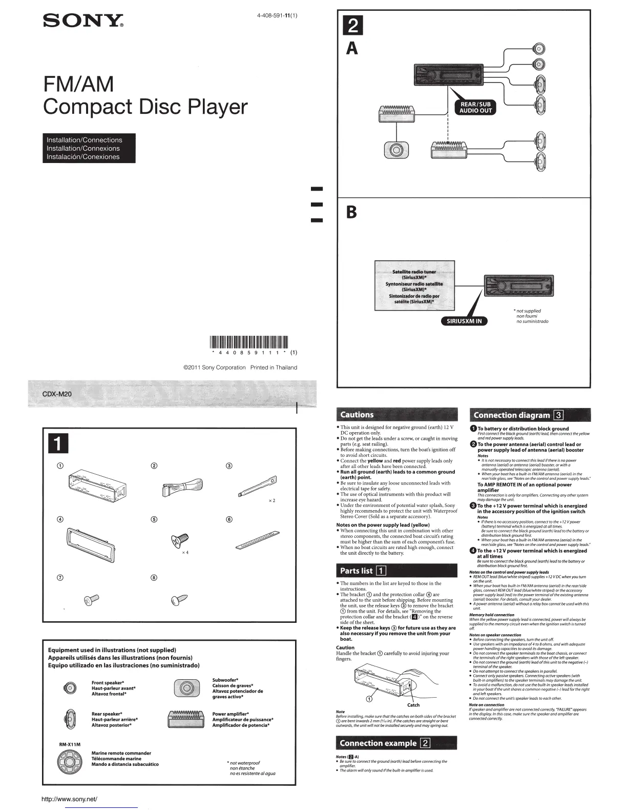
FM/AM
Compact Disc Player
lnstallat1on/Connect1ons
lnstallat1on/Connex1ons
lnstalac1on/Conex1ones
IIIIIIIIIUIIIIIIIIIIIIIIIIIIIIIIIIIIIIIIIIIIIIIIII~
• 4 4 0 8 5 9 1 1 1 • (1)
©201 1 Sony Corporation Printed
in
Th
ailand
D
(j)
®
~
~
@
®
~
X4
(j)
®
~
~
Equipment
used
in illustrations (not supplied)
Appareils utilises
dans
les illustrations (non fournis)
Equipo
utilizado
en
las ilustraciones {no suministrado)
RM-X11M
Front speaker*
Haut·parleur
avant*
Altavoz frontal*
Rear
speake,..
Haut·parleur
arriere*
Altavoz
posterior*
Marine remote commander
Telkommande marine
Mando a distancia subacuiitKo
http://www.sony.
neV
®
/
®
Subwoofer*
Caisson
de
graves*
Altavoz
potendador
de
graves activo*
x2
Power amplifier*
Ampllficateur
de
puissance*
Amplificador
de
potencia*
*nor
waterproof
noneranche
noe
s
re
siste
nte
a/
agua
-
-
-
f)
A
B
• This unit
is
designed for negative gro
un
d (ear
th
)
12
V
DC operation only.
• Do not get
th
e leads
und
er a scr
ew,
or
caught in moving
parts (e.g. seat ra
il
in
g).
• Befor
e making
connections,
turn
the boat's ignition off
to
avoid sh
or
t circuit
s.
• Connect the
yellow
and
red
power sup
pl
y leads only
after a
ll
other leads have been connected.
• Run all
ground
(earth)
leads
to
a
common
ground
(earth)
point.
•
Be
sure to insulate any loose unconnected leads with
electrical tape for safety.
• The use
of
optical instruments with this product
will
increase eye hazard.
• Und
er
the environment
of
poten
ti
al
wa
ter spl
as
h,
So
ny
highly recommends to protect the unit with Waterproof
Stereo Cover (Sold
as
a separate accessory).
Notes
on
the
power
supply
lead
(yellow)
• When connecting this unit in combination with other
stereo component
s,
the connected boat
ci
rcuit's rating
must be h
ig
her than the sum
of
each component's fuse.
• When no boat circuits are r
ated high enough, connect
the unit
dir
ectly to the battery.
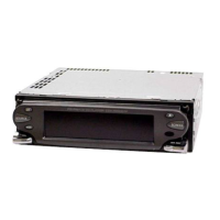
Parts list
[I]
• The numbers in the list are keyed to those in the
instructions.
• The bracket
G) and
th
e protection collar
@)
are
~~~a~~~~
~~!~~:~~:e~:~o~;shdr:~~~!~~~~:::o;r~~~!t
G) from the uni
t.
For details, see
~
R
emov
in
g
the
protection collar and the bracket
(
II
)" on the reverse
sid
eof
th
es
heet.
•
Keep
the
release
keys®
for
future
use
as
they
are
also
necessary
if
you
remove
the
unit
from
your
boat.
Caution
Handle the bracket G) carefully to avoid injuring your
fingers.
Not11
Before
installing, make
5ure
that the wtches an both
5ide5
of
the bracket
G) are bent inwards 2 mm
(l!
.,
in).lfrhecarches are straight or bent
outwards,
the unit will not
be
installed securely and may spring out.
Connection
example
W
Notnii)-AJ
•
lk
sure
to connect the ground (earth) lead before conneaing the
amplifier.
•
The
alarm will only sotmd
ifrhebuilt
-in amplifier
is
used.
•
not
supplied
nonfoumi
no suministrado
Connection
diagram
[]]
0To
battery
or
distribution
block
ground
First
connect the black ground (earth) lead, then connect the yellow
and
red
power supply
leads.
8To
the
power
antenna
(ae
rial)
control
lead
or
power
supply
lead
of
antenna
(aerial)
booster
Notes
•
lr
is
nor
necessary
to
connect this lead
if
there
is
no power
antenna (aerial) or
antenna (aerial) booster, or with a
manually-operated telescopic antenna (aerial).
•
When
your boor
has
o buifr-in
FMJAM
antenna (aerial} in the
reor/sideglass,
see
"Notes
on
rhe
control and power supply leads:
To AMP
REMOTE
IN
of
an
optional
power
amplifier
This
connection
Is
only for amplifiers. Connecting any other
system
may damage the vnit.
8To
the
+
12
V
power
terminal
which
Is
energized
in
the
accessory
position
of
the
ignition
switch
Notes
•
If
t
here
is
oo
accessory
position, connect
to
rhe
+
12
Vpower
(battery) terminal which
is
energized
at
all
times.
Be
svre
to connect
rhe
black.
ground (earth) lead
to
the battery or
disrributionblockgraundflrsr.
•
When
your boor
has
a built-in FM!AM antenna (aerial} in the
rear/side
glass,
see
NNo
r
es
on the control and power supply leads
."
0To
the+
12
V
power
terminal
which
is
energized
at
all
times
Be
sure
to
connect the block ground (earth) lead to the battery
or
distribution block ground first.
Notes on the control
cmd
power
supply leads
•
REM
OIJT
lead (blue/white striped)
supplies
+
12
V
DC
when you turn
on the unit.
• When
your boot
hds
bvilr-in
FM!AM
antenna (aerial) in the rear/side
glass
, connect
REM
OU
T lead (blue/white striped) ortheaccenoty
power supply lead
(red) to the power terminal
of
the existing antenna
(aerial)
booster.
For
derails, consult your
deoler.
• A power antenna (aerial) without a relay
box
cannot
be
used
with this
unit.
Mffmory
hold
conn«tion
When
t
he
yellow power supply lead
is
connected, power will
always
be
supplied
ro
the memorycircuir
even
when the Ignition switch
Is
turned
""
Note5
on
5PffQklfr connection
• /kforeconnectingrhespeakers,tumtheunitoff.
•
Use
speakers
with an impedance
of
4 to Bohms, and with adequate
power handling capacities
to
avoid its damage.
• Do
not connect the
speaker
terminals to the boat
chassis,
or connect
the terminals
of
the right
speakers
with those
of
the
left
speaker.
• Oo not
con
nect the gravnd
(ea
rth}
leodafthisvni
r
ro
rhe
negative(-}
terminalofthespeoker.
• Oo nor a
rr
empt to connect the
speakers
in parallel.
• Conneaonlypossive
speakers.
Connecting
<Ktive
speakers
(with
built-in amplifiers)
to
the speaker terminals may damage the unit
•
To
avoid a malfunction, do not
vse
the bui!Hn
speaker
leads
installed
in
yovrboat
if
the
un
it
shares
o common negative (-) lead for the right
and
left
speakers.
• Oonorconnecttheunir'sspeaker leadstoeachorher.
Note
on
cann«t/on
If
speaker
and amplifier ore nor connected couecrly, •
FAILURE
" appears
in
the display. In this
case,
make sure the
speaker
and amplifier are
connected correctly.