SECTION 5
DIAGRAMS
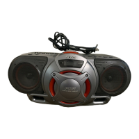
5-1. CIRCUIT BOARDS LOCATION
— 11 — — 12 —
BATT board
BATT COM board
POWER board
CONTROL-1 board
CONTROL-3 board
TUNER board
HEADPHONE board
LINE IN board
PRE board
MAIN board
LCD board
CD board
CONTROL-2 board
CD SECTION
Focus Bias Check
This check is to be done when the optical block replaced.
Check Procedure:
1. Connect the oscilloscope to test point TP (VC) and TP (RF) on
CD board.
2. Put the set into test mode.
3. Opitical pick-up setting to the center by + or – button pushing.
4. Insert disk (YEDS-18) and press u button.
5. Press the MODE button. (Tracking servo ON)
6. Check that the oscilloscope wavewform is as shown in the figure
below (eye pattern).
A good eye pattern means that the diamond shape (◊) in the
center of the waveform can be clearly distinguished.
7. Release test mode after adjustment is completed.
• RF signal reference waveform (eye pattern)
When observing the eye pattern, set the oscilloscope for AC range
and raise vertical sensivity.
[Adjustment Location : CD board] (Conductor side)
VOLT/DIV : 0.2V
TIME/DIV : 500n
0.9Vp-p – 1.3Vp-p
+
–
Oscilloscope
(DC range)
TP
(RF)
TP(VC)
 Loading...