Do you have a question about the Sony CRF-150 and is the answer not in the manual?
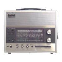
The Sony CRF-150 is a versatile FM/AM 13-band portable radio, designed for both general listening and shortwave enthusiasts. This service manual provides comprehensive details on its technical specifications, operational features, and maintenance procedures.
The CRF-150 operates as a high-performance portable radio, capable of receiving FM, MW, LW, and SW1-SW10 bands. Its core design utilizes a 2-FET, 19-transistor, 12-diode superheterodyne circuit, ensuring stable and clear reception across all bands.
The FM tuner section employs a low-noise junction FET for the mixer and a triple-tuned passive input circuit, which contributes to its strong signal reception and superior interference rejection. The FM oscillator generates a frequency 10.7 MHz higher than the incoming signal, which is then mixed to produce an IF signal. An AFC (Automatic Frequency Control) diode helps stabilize the local oscillator frequency. The FM IF amplifier boosts the 10.7 MHz IF signal, which is then fed to a limiter and an AM-FM mixer for further processing.
For AM reception, the radio features high-sensitivity and selectivity on SW bands, achieved through a double-superheterodyne front end. The AGC (Automatic Gain Control) circuit, comprising a transistor and a diode, automatically adjusts the gain of the IF amplifier to maintain a consistent output level regardless of signal strength. The first local oscillator generates frequencies that are mixed with the incoming signal to produce the first IF frequency. The first SW IF amplifier and MW, LW IF amplifier further process these signals. A second oscillator generates a 455 kHz signal, which is mixed with the output from the first IF amplifier. The FM IF amplifier also processes the 455 kHz AM IF signal.
The power supply circuit is designed for flexibility, allowing operation from six "D" size flashlight batteries, a 9-volt total, or household current (AC 100V, 117V, 220V, 240V). A reverse current flow prevention circuit protects the unit when batteries are inserted incorrectly or when the AC cord is used with batteries still in place.
The audio amplifier section features a volume control, treble and bass tone controls, and an OTL (Output Transformerless) push-pull class-B amplifier. Thermistors are used to stabilize the bias of the power transistors, and negative feedback from the output improves frequency response and reduces distortion.
The CRF-150 is designed for portability and ease of use. It features a telescopic antenna for FM and shortwave reception, and a built-in ferrite bar antenna for MW and LW. An external antenna terminal is also provided for enhanced reception. The radio includes a band selector switch (FM, MW, LW, SW1-SW10), an AFC ON/OFF switch for FM stability, and a selectivity switch (SHARP/BROAD) to optimize reception in varying signal conditions. A LOCAL/DX switch is also available to adjust sensitivity for local or distant stations.
The front panel includes six knobs for operation: calibrator, volume, tone (bass and treble), and two tuning knobs (AM and FM). A tuning meter assists in precise station tuning. The jack panel offers connections for MPX OUT, AUX IN, REC OUT, and earphones, expanding the radio's functionality for recording, external audio input, and private listening.
The service manual provides detailed instructions for disassembly, adjustment procedures, and a comprehensive electrical parts list, making maintenance and repair straightforward.
The chassis can be removed by pulling off the six control knobs, removing screws for the carrying handle, battery lid, and front panel. Specific instructions are provided for removing the FM tuner, SW tuner, CP/IF circuit board, power supply circuit board, and AF circuit board. Detailed steps are also included for dial scale and dial drum removal and reassembly, as well as dial cord restringing, which is crucial for maintaining accurate tuning.
The manual outlines precise alignment procedures for both IF and frequency coverage/tracking.
The manual includes comprehensive schematic diagrams for the entire radio, along with detailed mounting diagrams for each circuit board (FM Tuner, SW2-SW10 Front End, CP/IF, AF, Power Circuit Board, and Jack Panel). A wiring diagram illustrates the interconnections between different sections. An electrical parts list provides part numbers, descriptions, and specifications for all components, including semiconductors, coils, capacitors, resistors, and miscellaneous parts.
Instructions for packing the radio and an exploded view diagram are provided, showing the assembly of various components and their part numbers, which is useful for reassembly and identifying parts.
Overall, the Sony CRF-150 is a robust and feature-rich portable radio, supported by a thorough service manual that ensures its longevity and maintainability.
| Brand | Sony |
|---|---|
| Model | CRF-150 |
| Category | Portable Radio |
| Language | English |