EasyManua.ls Logo

Sony CRF-150 - Technical Features; Circuit Description

Sony CRF-150
45 pages
Print Icon
To Next Page IconTo Next Page
To Previous Page IconTo Previous Page
Loading...
150
1-2.
TECHNICAL
FEATURES
*
High-performance
portable
radio
receiver
with
thirteen
bands;
FM,
MW,
LW,
SWI-SWIO.
*
FET
(field
effect
transistor)
with
tripletuned
passive
input
circuit
for
superior
interference
rejection.
*
High-sensitivity
and
selectivity
on
SW
bands
using
double-superheterodyne
front
end.
*
High-fidelity
af
amplifier
with
OTL
circuit.
*
Choice
of
three
power
sources;
house
current,
battery,
car
battery.
1:3.
CIRCUIT
DESCRIPTION
Stage/control
Function
Fm
Tuner
FET
mixer
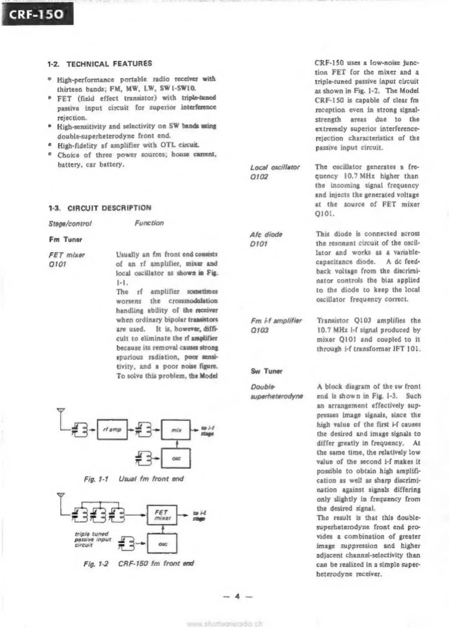
Usually
an
fm
front
end
consists
ото!
of
an
rf
amplifier,
mixer
and
local
oscillator
as
shown
in
Fig.
I1.
The
rf
amplifier
sometimes
worsens
the
crossmodulation
handling
ability
of
the
receiver
when
ordinary
bipolar
transistors
are
used,
It
is,
however,
diffi
cult
to
eliminate
the
rf
amplifier
because
its
removal
causes
strong
spurious
radiation,
poor
sensi-
tivity,
and
а
poor
noise
figure.
To
solve
this
problem,
the
Model
Fig.
1-1
Usual
fm
front
end
Fig.
12
CRF-150
fm
front
end
Local
oscillator
0102
Afc
diode
D101
Fm
Ы
amplifier
0103
CRF-150
uses
a
low-noise
junc-
tion
FET
for
the
mixer
and
a
triple-tuned
passive
input
circuit
as
shown
in
Fig.
1-2.
The
Model
CRF-150
is
capable
of
clear
fm
reception
even
in
strong
signal-
strength
areas
due
to
the
extremely
superior
interference-
rejection
characteristics
of
the
passive
input
circuit,
The
oscillator
generates
a
fre-
quency
10.7
MHz
higher
than
the
incoming
signal
frequency
and
injects
the
generated
voltage.
at
the
source
of
FET
mixer
0101.
This
diode
is
connected
across
the
resonant
circuit
of
the
oscil-
lator
and
works
as
a
variable-
capacitance
diode.
А
dc
feed
back
voltage
from
the
discri
nator
controls
the
bias
applied
to
the
diode
to
keep
the
local
oscillator.
frequency
correct.
Transistor
Q103
amplifies
the
10.7
MHz
i-f
signal
produced
by
mixer
0101
and
coupled
to
it
through
Hf
transformer
IFT
101.
A
block
diagram
of
the
sw
front
end
is
shown
in
Fig.
1-3.
Such
an
arrangement
effectively
sup-
presses
image
signals,
since
the
high
value
of
the
first
i4
causes
the
desired
and
image
signals
to
differ
greatly
in
frequency.
At
the
same
time,
the
relatively
low
value
of
the
second
if
makes
it
possible
to
obtain
high
amplifi-
cation
as
well
as
sharp
discrimi-
mation
against
signals
differing
only
slightly
in
frequency
from
the
desired
signal.
The
result
is
that
this
double-
superheterodyne
front
end
pro-
vides
a
combination
of
greater
image
suppression
and
higher
adjacent
channel-selectivity
than
can
be
realized
in
a
simple
super-
heterodyne
receiver.