9
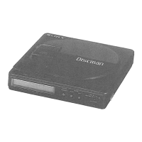
D-SJ301
Pin No. Pin name I/O Description
105 VDD2–Power supply terminal for digital.
106 LRCK O LR clock output for D/A interface.
107 LRCKI I LR clock input for D/A interface.
108 PCMD O Serial data output for D/A interface.
109 PCMDI I Serial data input for D/A interface.
110 BCK O Bit clock output for D/A interface.
111 BCKI I Bit clock intput for D/A interface.
112 DVDD – Power supply for DRAM interface.
113A3ODRAM adress 3.
114A2ODRAM adress 2.
115A1ODRAM adress 1.
116A0ODRAM adress 0.
117 A10 O DRAM adress 10.
118A11 I/O Not used (OPEN).
119 TEST3 O Not used (OPEN).
120 TEST4 O Not used (OPEN).
Pin No. Pin name I/O Description
IC801 T5AW5-SP-M1 (SYSTEM CONTROL)
1 GND – Ground terminal.
2 XIN I System clock input (4.19MHz).
3 XOUT O System clock output (4.19MHz).
4 TEST I Test mode terminal (Fixed to “L”).
5 VDD1 – Power supply for CPU & I/O.
6 P21 – Not used (OPEN).
7 P22 I Not used (Fixed to “H”).
8 RESET I/O Reset terminal.
9 FOK.I I FOK detection input.
10 XRST_0 O Reset signal output.
11 SCOR_I I SCOR pulse input.
12 GRSCOR_I I GRSCOR input.
13 AMTE_O O Analog mute output.
14 XSOE_O O Serial enable output.
15 XLAT_O O Serial latch output.
16 MSDTI I Serial data input from DSP SENS.
17 MSDTO O Serial data output.
18 MSCK_O O Serial interface clock output.
19 VCPU – Power supply for CPU and I/O.
20 VREF_AD – Analog reference voltage for A/D converter.
21 AD_CHGMON1 I Charge monitor input.
22 AD_BATMNT I Battery monitor input.
23 AD_KEY2 I Key input.
24 AD_SEL I Version select terminal.
25 AD_KEY I Set’s key detection input.
26 AD_VOL I Volume control input.
27 AD_DCINMNT I DC voltage monitoring input.
28 OPEN_I I OPEN switch status detection input.
29 PPG – Not used (OPEN).
30 BEEP_O O Beep sound output.
 Loading...