EasyManua.ls Logo

Sony D-99 Service Manual

Sony D-99
23 pages
To Next Page IconTo Next Page
Page #1 background imageLoading...
Page #1 background image
CD
section
System
Laser
diode
properties
Spindle
speed
Scan
velocity
Error
correction
D-A
conversion
Frequency
response
Wow
and
flutter
Outputs
(at
9
V
input
level)
“*Measured
by
EIAJ
CP-307
General
Power
requirements
CAUTION
SPECIFICATIONS
Compact
disc
digital
audio
system
Material:
GaAlAs
Wavelength:
780
nm
mission
duration:
Continuous
Laser
output:
Less
than
44.6.W*
*This
output
is
the
value
measured
at
a
distance
of
200
mm
from
the
objective
lens
surface
on
the
Optical
Pick-up
Block.
500
r.p.m.
to
200
r.p.m.
(CLV)
1.2-1.4
m/sec.
Sony
Super
Strategy
Cross
Interleave
Reed
Solomon
Code
{-bit
quarz
time-axis
control
20-20,000
Hz
*2dB
Below
measurable
limit’
*
Line
output
(stereo
minijack)
Output
level
1.0
V
rms
at
50
kilohms
Load
impedance
over
10
kilohms
Headphones
(stereo
minijack)
9mW
+
9
mW
at
16
ohms
Rechargeable
battery
pack
BP-2EX
(supplied)
Battery
case
EBP-2
(supplied)
and
two
size
AA
(LR6)
alkaline
batteries
(optional)
DC
IN
9
V
jack
accepts:
Sony
AC
power
adaptor
(supplied)
-—
Continued
on
page
2
Use
of
controls
or
adjustments
or
performance
of
pro-
cedures
other
than
those
specified
herein
may
result
in
hazardous
radiation
exposure,
COMPACT
DI
US
Model
Canadian
Model
AEP
Model
UK
Model
E
Model
DISstmMaN
Model
Name
Using
Similar
Mechanism
|
D-9,//90
CD
Mechanism
Type
CDM-90
Question and Answer IconNeed help?

Do you have a question about the Sony D-99 and is the answer not in the manual?

Sony D-99 Specifications

General IconGeneral
TypePortable CD Player
ModelD-99
DAC1-bit
Battery2 x AA
Power supply3V DC
Disc formatCD
Frequency Response20 - 20000 Hz ±1 dB

Summary

Specifications

CD Section Specifications

Details about the CD playback system and laser diode properties.

General Specifications

Power requirements and operating conditions for the device.

Section 1 GENERAL

Location and Function of Controls

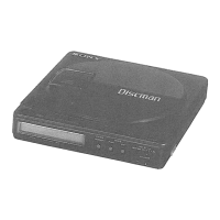
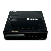
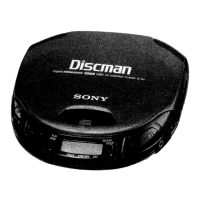
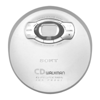
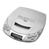
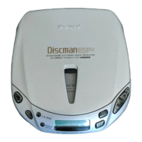
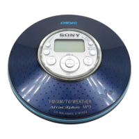
Identifies and explains the external buttons and controls of the player.

Section 2 SERVICING NOTES

Handling the Optical Pick-up Block

Precautions for handling the sensitive optical pick-up block.

Before Replacing the Optical Block

Procedures and checks before replacing the optical block.

Flexible Circuit Board Repairing

Guidelines for soldering and repairing flexible circuit boards.

Notes on Chip Component Replacement

Precautions for replacing surface-mount components.

Service Mode Operations

Laser Diode Emission Check Procedures

Steps to check if the laser diode is emitting light.

Service Mode Setting Method

Steps to enter the service mode.

Service Mode Operation Steps

Describes the functions and operations within service mode.

Service Mode Release

Procedures to exit the service mode.

IC301 CXD8178Q Terminal Explanations

Section 3 ELECTRICAL ADJUSTMENTS

Notes on Adjustment

General guidelines and precautions for performing adjustments.

Preparation and Checks

Steps to prepare for adjustments and perform initial checks.

+3.4V Adjustment

Procedure for adjusting the +3.4V power supply.

+3.6V Adjustment

Procedure for adjusting the +3.6V power supply.

PLL Free Run Frequency Check and Adjustment

Checking and adjusting the PLL free run frequency.

+3.9V Adjustment

Procedure for adjusting the +3.9V power supply.

Electrical Adjustment Procedures

Tracking Balance Adjustment

Procedure to adjust the tracking balance.

RF Signal Reference Waveform

Description of the RF signal eye pattern.

Focus Bias Adjustment

Procedure to adjust the focus bias.

Adjustment Parts Location Diagram

Illustrates locations of adjustment components on the main board.

Reference and Jig Connections

Focus/Tracking Gain Adjustment

Explains the focus/tracking gain adjustment, noting its difficulty.

CD Jig Connection

Details how to connect the CD jig for adjustments.

Section 4 Diagrams

Block Diagrams

High-level overview of the player's internal circuitry.

Diagram Layouts

PC Board, Switch, and Motor Layouts

Visual layout of key components on the circuit boards.

LCD Module Display

Explains the segments and display modes of the LCD.

Semiconductor Lead Layouts

Printed Wiring Boards and Semiconductor Locations

Printed Wiring Boards

Shows the physical layout of traces on the main circuit boards.

Semiconductor Locations

Pinpoints the physical location of semiconductors on the boards.

Schematic Diagrams

IC Block Diagrams

Section 5 Exploded Views

Upper/Bottom Section

Exploded view of the player's main mechanical parts.

Mechanism Exploded View

Section 6 Electrical Parts List

Capacitors

List of capacitors with part numbers and values.

Resistors

List of resistors with part numbers and values.

Coils

List of coils with part numbers and values.

Semiconductors

List of semiconductors with part numbers.

Accessory and Packing Material List

Related product manuals