EasyManua.ls Logo

Sony D-5 User Manual

Sony D-5
46 pages
To Next Page IconTo Next Page
Page #1 background imageLoading...
Page #1 background image
MICROFILM
System
Disc
Laser
Spindle
speed
Scan
velocity
Error
correction
Number
of
channels
D-A
conversion
Frequency
response
Harmonic
distortion
Dynamic
range
Channel
separation
Wow
and
flutter
Outputs
Disc
Track
pitch
Sampling
frequency
Quantization
Modulation
system
Transfer
rate
SPECIFICATIONS
Compact
disc
digital
audio
system
Compact
disc
Semiconductor
laser
(A
=
780
nm)
200
r.p.m.
to
500
r.p.m.(CLV)
1.2-1.4
misec.
Sony
Super
Strategy
Cross
Interleave
Read
Solomon
Code
2
16-bit
linear
20-20,000
Hz
*3.dB
Less
than
0.008
%
(1
kHz)
(Mode!
D-5)
Less
than
0.0095
%
(1
kHz)
(Model
D-50)
More
than
90
dB
(1
kHz)
More
than
85
dB
(1
kHz)
(Model
D-5)
More
than
82
dB
(1
kHz)
(Model
D-50)
Below
measurable
limit
Line
output
(stereo
minijack)
Output
level
1.6V
rms
(at
MSB)
Load
impedance
over
10
kilohms
Headphones
(stereo
minijack)
10
mW
+10mW
at
32
ohms
1.6un)
44,1kHz
16
bit
linear
quantizing/channel
EFM
2.03
Mbit/sec.
(before
modulation)
SAFETY-RELATED
COMPONENT
WARNING!!
COMPONENTS
IDENTIFIED
BY
SHADING
AND
MARK
A
ON
THE
SCHEMATIC
DIAGRAMS
AND
IN
THE
PARTS
LIST
ARE
CRITICAL
TO
SAFE
OPERATION.
REPLACE
THESE
COMPONENTS
WITH
SONY
PARTS
WHOSE
PART
NUMBERS
APPEAR
AS
SHOWN
IN
THIS
MANUAL
OR
IN
SUPPLEMENTS
PUBLISHED
BY
SONY.
Generai
Power
requirements
Power
consumption
Dimensions
Weight
D5:
US
Model
D-50:
AEP
Model
UK
Model
E
Model
Ose
DIGITAL
AUDIO
DC
9V,
six
atkatine
batteries,
size
C
(IEC
designation
LR14)
or
six
KR-C-F-2
nickel-cadmium
rechargeable
batteries
used
in
optional
Sony
EBP-
9LC
battery
case
DC
IN
9V
jack
accepts;
Sony
ac
power
adaptor
(supplied)
for
use
on
120V
ac,
60
Hz
or
Sony
DCC-120
car
battery
cord
(optional)
for
use
on
12V
car
battery
4wW
Approx.
127
x36.9«
132.5
mm
(wih/d)
(5x
14x5¥,
inches)
not
incl.
projecting
parts
and
controls
Approx.
127.542
«133mm
(w/h/d)
(5/4
1¥,x5/, inches)
incl.
projecting
parts
and
controls
Approx.
590g
(1b
5
0z),
net
COMPACT
DISC
COMPACT
PLAYER
SON
Y.
Question and Answer IconNeed help?

Do you have a question about the Sony D-5 and is the answer not in the manual?

Sony D-5 Specifications

General IconGeneral
BrandSony
ModelD-5
CategoryCD Player
LanguageEnglish

Summary

Specifications

General Specifications

Details general operating parameters, power, dimensions, and weight.

Safety Related Component Warning

Features

Section 2: Disassembly and Reassembly

2-1. Disassembly

Step-by-step instructions for dismantling the device.

2-2. Mechanical Section Reassembly

Procedures for reassembling mechanical parts.

2-3. Mechanical Adjustments

Steps for calibrating mechanical components after reassembly.

Section 3: Adjustments

3-1. Electrical Adjustments

Procedures for calibrating electrical parameters and waveforms.

Section 4: Diagrams

4-1. Mounting Diagram

Shows the physical placement of components on circuit boards.

4-2. Schematic Diagram

Provides detailed circuit schematics for troubleshooting.

Section 5: Exploded Views and Parts List

Protection of Eyes from Laser Beam During Servicing

Caution for Electrostatic Breakdown

Handling the Optical Pick-up Block

Precautions for safely handling the sensitive optical pick-up unit.

Chip Component Indications

2-Letter Method (EIAJ RC-3699)

Details the 2-letter coding system for chip components.

3-Number Method

Explains the 3-number coding system for chip components.

4-Letter Method (for Capacitor)

Describes the 4-letter coding system used for capacitors.

Replacing Chip Components

Precautions for Replacement

Essential steps to prevent damage during chip component replacement.

Removing Chip Components

Procedures for safely detaching chip components from the board.

Connecting Chip Components

Methods for soldering new chip components onto the board.

Flexible Circuit Board Repairing

Notes on Opening Main Board

Notes on Replacing IC801 (Model D-5 Only)

Caution on DC-DC Converter Replacement

Service Mode (Service Program)

Service Mode Operation Steps

Step 1: Setting Method

How to prepare and enter the service mode.

Step 2: Operation

Instructions for performing tests and checks in service mode.

Step 3: Release

Procedure for exiting the service mode.

Main Board (Double-sided) Check

Laser Diode Check Procedure

Procedure 1

First method for checking laser diode function using service mode.

Procedure 2

Second method for checking laser diode function via component label.

PC Boards/Switch/Motor Layouts

Main Board IC Layouts

Identifies the integrated circuits mounted on the main circuit board.

Notes on Moisture Condensation

Notes on Compact Discs

Maintenance

Cleaning the Lens

Instructions for cleaning the optical lens to ensure playback quality.

Location and Function of Controls

Front Panel Controls

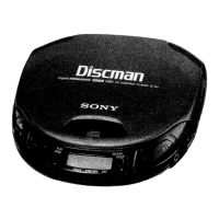
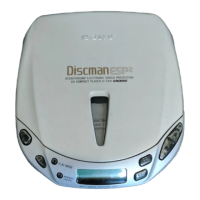
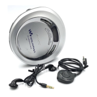
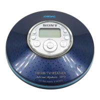
Identifies and describes controls found on the front of the player.

Display Indicators

Explains the meaning of indicators shown on the display window.

Rear Panel Controls

Identifies and describes controls located on the rear panel.

Disc Playing Operations

Describes how to play a disc and control playback functions.

Using the Time Counter

Monitor Elapsed Playing Time

How to view the time elapsed within a track.

Monitor Remaining Playing Time

How to view the time remaining on the disc.

Lead Wire Arrangement

Section 1: Outline

1-1. Block Diagram

Shows the functional block diagram of the audio circuit.

Section 2: Disassembly and Reassembly

2-1. Disassembly

Step-by-step instructions for dismantling the device.

2-2. Mechanical Section Reassembly

Procedures for reassembling mechanical parts.

2-3. Mechanical Adjustments

Steps for calibrating mechanical parts like sled motor and rotor.

Section 3: Adjustments

3-1. Electrical Adjustments

Procedures for calibrating electrical parameters and waveforms.

Electrical Adjustment Procedures

Tracking Balance Adjustment

Adjusting tracking balance for proper pick-up follow-up.

Sled Motor Offset Check and Adjustment

Checking and adjusting sled motor offset for smooth operation.

Focus Bias Adjustment

Adjusting focus bias for optimal eye pattern.

Focus/Tracking Gain Adjustment

PLL Free Run Frequency Check and Adjustment

Electrical Parts List

Diagrams

Semiconductor Lead Layouts

Diagrams showing pin configurations for semiconductor components.

Exploded Views and Parts List

Electrical Parts Breakdown

Accessory & Packing Material

Related product manuals