— 12 —
Focus bias Check
Condition:
• Hold the set in horizontal state.
Check Procedure:
1. Set the equipment to service mode stop state. (See page 10.)
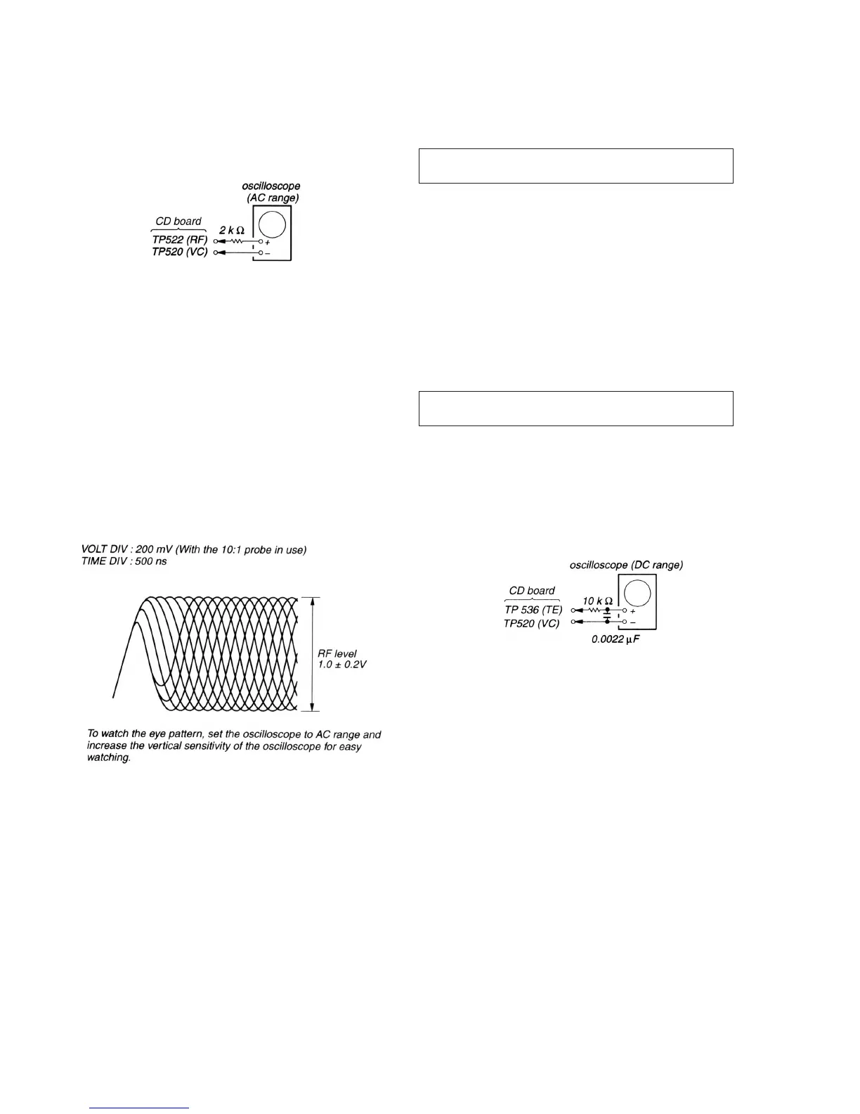
2. Connect the oscilloscope to the test point TP522 (RF) of the
CD board.
3. Move the optical pick-up by pressing the + and = keys.
4. Put the disc (YEDS-18).
5. Press the ^ key.
From focus searching, focus is turned ON while entering
CLV drawing-in mode. Tracking and sled are turned OFF.
6. Press the PLAY MODE key. (Both tracking and sled are turned
ON.)
7. Check the oscilloscope waveform is as shown below.
A good eye pattern means that the diamond shape (≈) in the
center of the waveform can be clearly distinguished.
RF SIGNAL REFERENCE WAVEFORM (EYE PATTERN)
8. Stop revolving of the disk motor by pressing the p key.
9. After the completion of adjustment, reset service mode. (See
page 10.)
Check Location: CD board (See page 14.)
[
]
Focus/Tracking Gain Adjustment
A servo analayzer is necessary in order to perform this adjustment
exactly.
However, this gain has a margin, so even if it is slightly off,
there is no problem. Therefore, do not perform this adjustment.
Focus/tracking gain determines the pick-up follow-up relative to
mechanical noise and mechanical shock when the 2-axis device
operates. However, as these reciprocate, the adjustment is at the
point where both are satisfied.
• When gain is rased, the noise when 2-axis device operates
increase.
• When gain is lowered, it is more susceptible to mechanical shock
and skipping occurs more easily.
This adjustment has to be performed upon replacing any of the
following parts.
• Optical pick-up
• RV503 (Focus gain VR)
• RV502 (Tracking gain VR)
Normally, be sure not to move RV503 (focus gain VR) and
RV502 (tracking gain VR).
Adjustment method:
– Focus Gain Adjustment –
This adjustment is not performed.
If focus gain VR RV503 is turned, set to mechanical center.
– Tracking Gain Adjustment –
(perform at normal operation)
1. Place the optical pick-up level, horizontally. (If the optical pick-
up is not level, the 2-axis device will be weighted and adjustment
cannot be done.)
2. Connect the oscilloscope TP536 (TE) and TP520 (VC) on CD
board.
3. Set the disk (YEDS-18) and press the ( (+) key.
4. Turn RV502 slightly clockwise (tracking gain drops) and obtain
a waveform with a fundamental wave (waveform has large
waves) as in Figure 1.
5. Turn RV502 slowly counterclockwise (tracking gain rises) until
the fundamental wave disappears (no large waves) as in Figure
2.
6. Set RV502 to the position about 30° counterclockwise form the
position obtained in step 5. If RV502 contact point is more than
90° counterclockwise from mechanical center, tracking gain is
too high. In this case, readjust from step 4.
7. Press ( (+) or = key and observe the 100 track jump
waveform. Check that no traverse waveform appears for both
( (+) or = key and observe the 100 track jump
waveform. Check that no traverse waveform appears for both
( (+) or = directions. (See Figures 3 and 4.) It is
acceptable if the traverse waveform appears only now and then,
but if it appears constantly, raise tracking gain slightly and check
step 7 again.
8. Check that there is not abnormal amount of operation noise
(white noise) from the 2-axis device. If there is, tracking gain is
too high, readjust starting with step 4.



 To Next Page