2-10E
DCR-DVD91E/DVD101/DVD101E
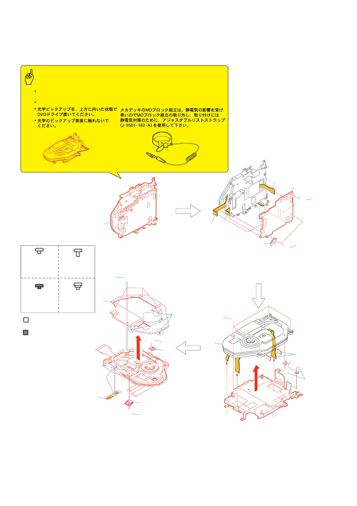
2-1. DISASSEMBLY
The following flow chart shows the disassembly procedure.
MD-104
M
D-104
Screw
M1.7x2.5
3-078-889-11
Silver
Black
Screw
M1.4x2.5
3-084-681-01
F
Screw
M1.7x2.5
3-092-019-01
H
D
Screw
M1.7x2
3-703-816-14
G
1
Four PWH screws (M1.4x2.5) silver
2
Two screws (M1.7x2.5) silver
3
FK spring
4
MD frame assembly
5
Two OP sheets
6
DDX-A1010
1
Five screws (M1.4
×
2) black
2
Three claws
3
Ornamental plate assembly
4
Screw (M1.4
×
2) black
5
Gatatori spring
F
G
G
G
D
D
2
4
6
3
5
1
1
3
9
6
7
8
5
4
2
MD block assembly
6
Screw (M1.4
×
2) black
7
Rack claw
8
Remove the soldering
9
FP-629 flexible board
1
Two screws (M1.7x2.5) silver
2
Retainer sheet metal (JS)
3
Screw (M1.7x2.5) silver
4
to
7
CN4851 (6P), CN4801 (15P) CN4852 (20P)
CN4501 (40P) of MD-104 board
8
MD-104 board
4
5
6
D
1
3
2
H
7
8
Optical pickup
Caution
Precautions during handling
Be sure to place the DVD drive with its
optical pickup facing upward.
Do not touch the optical pickup surface.
(J-2501-162-A)
Use the adjustable wrist strap (J-2501-162-A) as the
preventive measure for static electricity when the
removing and installing the MD black assembly because
the MD black assembly of this mechanism beck is easily
affected by the static electricity.