DCR-PC53E/PC55/PC55E
2-1 2-2
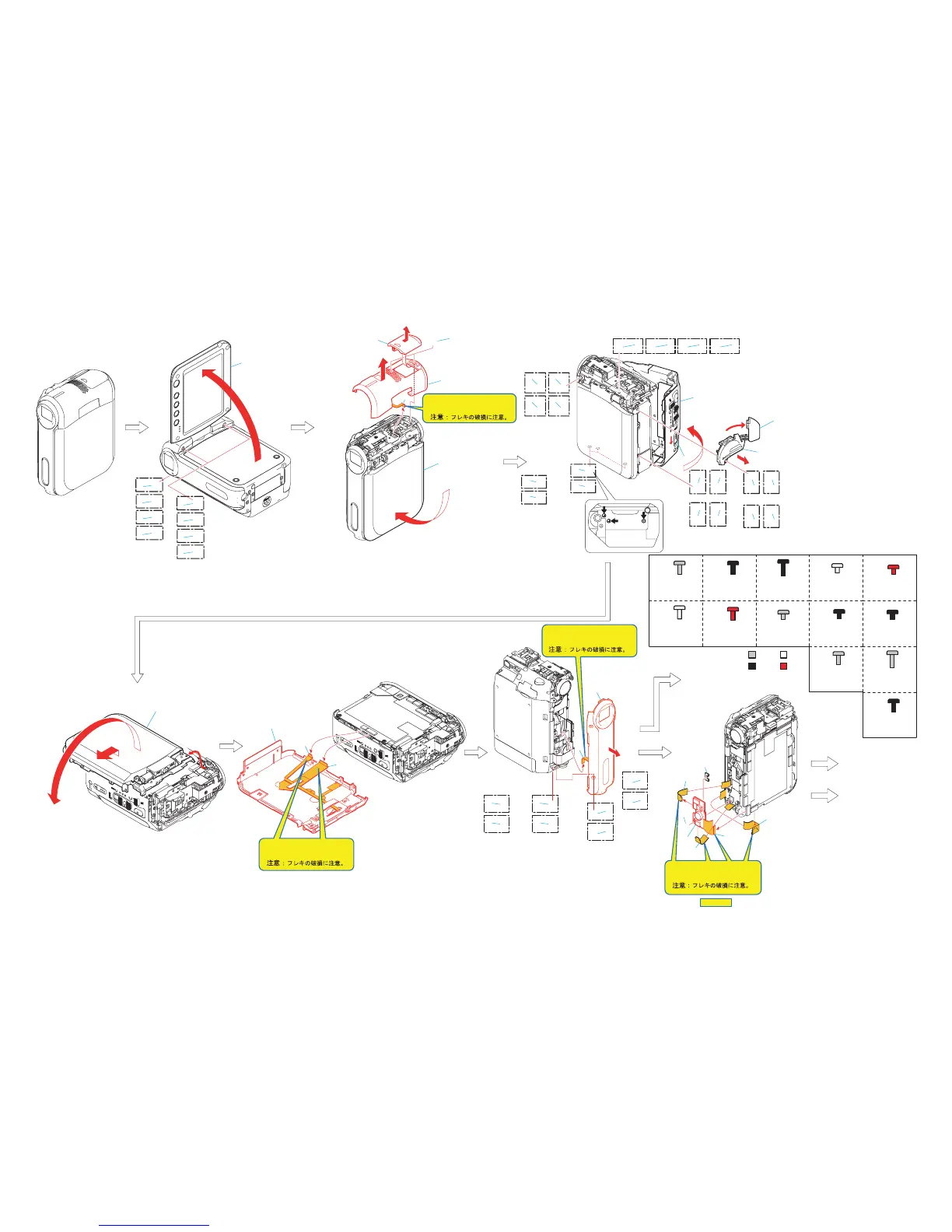
2-1. DISASSEMBLY
The following flow chart shows the disassembly procedure.
2. DISASSEMBLY
Cabinet (L) section
(See page 2-5)
3
2
2
3
4
5
1
A
3
12
B
E
C
1
Screw (M1.7x4)
(Silver)(White)(Black)(Red)
2
Open the LCD block.
3
Two screws (M1.7x4)
(Silver)(White)(Black)(Red)
1
Closes the LCD block.
2
Remove the shoe cover assembly
in the direction of the arrow a.
3
Two screws (M1.7x6) black
4
Remove the top cabinet assembly
in the direction of the arrow b.
5
Microphone (8P)
1
FP-053 flexible board (27P)
2
FP-222 flexible board (11P)
3
Cabinet (R) assembly
1
FP-049 flexible board (14P)
2
FP-042 flexible board (31P)
3
Screw (M1.7x2.5) silver
4
FB-223 boaed
5
Control switch block (13P)
6
FP-050 flexible board (6P)
7
Gyro cushion
Note:
Be very careful not to
damage the flexible board.
Note:
Be very careful not to
damage the flexible board.
1
2
3
7
4
5
6
F
A
VC-379 board section
(See page 2-3)
B
Hinge section
(See page 2-3)
Silver
White
Black
Red
Tapping screw
M1.7x3.5
3-080-204-01
Tapping screw
M1.4x4
3-348-998-61
Tapping screw
M1.7x5
3-080-204-21
Screw
M1.7x4
3-056-030-91
Screw
M1.7x4
3-084-523-31
Screw
M1.7x6
3-080-198-51
Screw
M1.7x2.5
3-084-523-11
Screw
M1.7x2.5
3-057-082-01
A
Screw
M1.7x4
3-056-030-91
B
Screw
M1.4x1.5
3-062-214-01
a
a
b
c
d
b
HELP 01
D
Screw
M1.7x4
3-084-523-31
C
E
F
Screw
M1.7x2.5
3-057-082-01
G
I
Screw
M1.7x2.5
3-084-523-11
H
J
K
L
M
3
C
3
D
1
A
1
B
(Silver)
(White)
1
C
(Black)
1
D
(Red)
2
4
5
A
2
B
(Silver)
(Black)
2
C
2
D
(White)
(Red)
6
7
8
A
6
C
(Silver)
(Black)
6
B
6
D
(White)
(Red)
3
F
3
G
(Silver)
(White)
3
H
3
I
(Black)
(Red)
2
3
1
Note:
Be very careful not to
damage the flexible board.
9
1
F
F
1
G
H
(Silver)
(Silver)
9
(Black)
9
G
I
(White)
9
(Red)
(White)
1
H
1
I
(Black)
(Red)
1
Screw (M1.7x2.5)
(Silver)(White)(Black)(Red)
2
Screw (M1.7x4)
(Silver)(White)(Black)(Red)
3
Screw (M1.7x2.5)
(Silver)(White)(Black)(Red)
4
Slide the eject knob in the direction
of the arrow a.
5
Open the cabinet (L) assembly in
the direction of the arrow b.
6
Screw (M1.7x4)
(Silver)(White)(Black)(Red)
7
Open the jack cover (L) in the direction
of the arrow c.
8
Remove the MS cabinet assembly
in the direction of the arrow d.
9
Screw (M1.7x2.5)
(Silver)(White)(Black)(Red)
2
1
A
A
1
B
2
B
1
Screw (M1.7x4)
(Silver)(White)(Black)(Red)
2
Screw (M1.7x4)
(Silver)(White)(Black)(Red)
3
Remove the faont panel assembly
in the direction of the arrow a.
4
Motor unit (8P)
a
a
b
(Silver)
(Silver)
(Black)
2
C
2
D
(White)
(Red)
(White)
1
C
1
D
(Black)
(Red)
1
Remove the cabinet (R) assembly
in the direction of the arrow a.
2
Remove the cabinet (R) assembly
in the direction of the arrow b.
4
3
Note:
Be very careful not to
damage the flexible board.
(Silver)
(White)
(Black)
(Red)