2-9
2. DISASSEMBLY
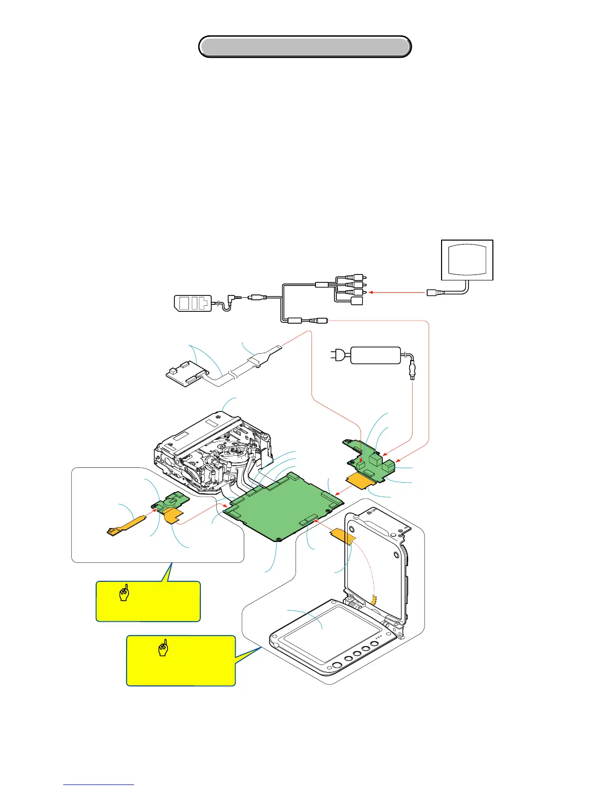
2. DISASSEMBLY
DCR-PC53E/PC55/PC55E
1
8
I/F unit for LANC control
(J-6082-521-A)
CPC-15
(J-6082-564-A)
AC power
adaptor
AC IN
J8601
CN8505
CN8501
DC-IN
Monitor TV
FP-044 flexible
board (80P)
FP-050 flexible
board (6P)
FP-042 flexible
board (37P)
CR-049 board
VC-379 board
FP-053
LCD block
FB-223 board
Connect only when checking
for ejection.
Connect this only when using
the LCD and the touch panel.
Mechanism deck
CN8004
CN1008
CN1002
CN1006
CN1005
CN1003
CN1009
CN1013
VC-379
FB-223
CR-049
[SERVICE POSITION TO CHECK THE VTR SECTION]
Connection to Check the VTR Section
To check the VTR section, set the VTR to the "Forced VTR power ON" mode.
Operate the VTR functions using the adjustment remote commander (With the HOLD switch set in the OFF position).
Setting the "Forced VTR Power ON" mode
1) Select page: 0, address: 01, and set data: 01.
2) Select page: 0, address: 10, and set data: 00.
3) Select page: A, address: 10, set data: 02, and press the
PAUSE button of the adjustment remote commander.
Exiting the "Forced VTR Power ON" mode
1) Select page: 0, address: 01, and set data: 01.
2) Select page: 0, address: 10, and set data: 00.
3) Select page: A, address: 10, set data: 00, and press the
PAUSE button of the adjustment remote commander.
4) Select page: 0, address: 01, and set data: 00.
Caution
Caution
Adjustment remote
commander (RM-95)
A/V
Video (Yellow)
Multi cable for service
(J-6082-535-A)