4-65
DCR-TRV22/TRV22E
COVER
COVER
4-3. PRINTED WIRING BOARDS
4-3. PRINTED WIRING BOARDS
(For printed wiring boards)
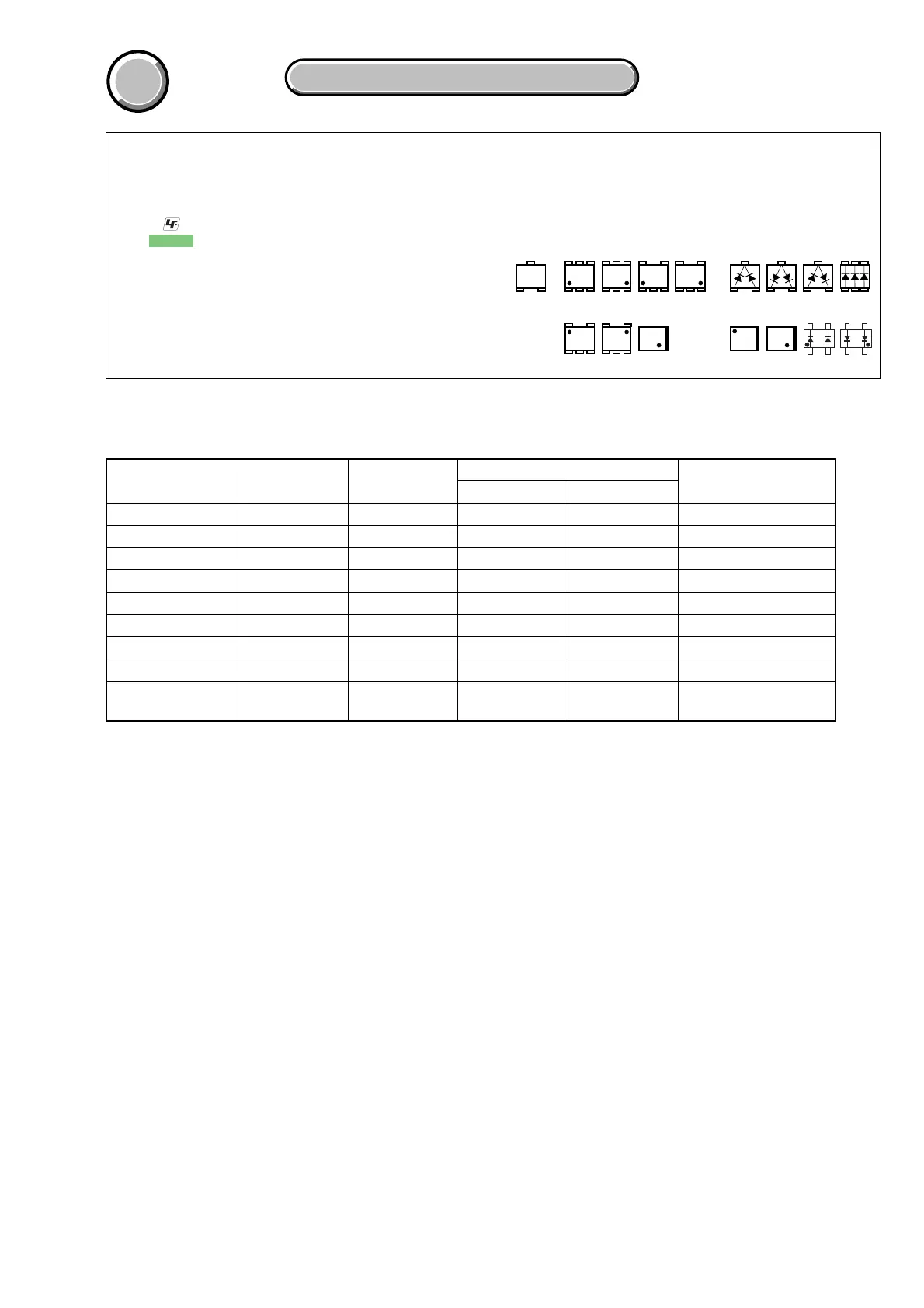
• : Uses unleaded solder.
• : Pattern from the side which enables seeing.
(The other layers’ patterns are not indicated)
• Through hole is omitted.
• Circled numbers refer to waveforms.
• There are a few cases that the part printed on diagram
isn’t mounted in this model.
• C: panel designation
THIS NOTE IS COMMON FOR WIRING BOARDS
(In addition to this, the necessary note is printed in each block)
21
3
21
3
21
3
345
21
123
654
EB
C
31
5
5
2
46
123
54
43
12
12
43
312
45
534
12
34
21
12
43
46
2
5
31
12
4
3
• Chip parts.
Transistor Diode
board name
CD-430
LB-085
FP-626 FLEXIBLE
VA-118
CK-129
PD-188
JK-242
MA-421
VC-312
parts location
(shown on page)
4-93
4-93
–
4-93
4-94
4-94
4-94
4-94
4-95
waveform
(shown on page)
4-89
–
–
4-89
–
4-90
–
–
4-91,4-92
number of layers
6
6
1
6
6
6
6
6
8
layers not shown
2 to 5
2 to 5
–
2 to 5
2 to 5
2 to 5
2 to 5
2 to 5
2 to 7
CSP IC
–
–
–
–
–
–
–
–
IC2101, 2201, 2301,
2601, 2704, 2803
pattern
BOARD INFORMATION





 To Next Page