Do you have a question about the Sony DCR-TRV240 and is the answer not in the manual?
Details on recording system, image device, lens, and signals.
Lists all connectors and LCD screen specifications.
Covers power requirements, operating temps, dimensions, mass, viewfinder.
Specifications for AC adaptor and battery pack, including InfoLITHIUM.
Details flash memory capacity, operating voltage, dimensions, and mass.
Warning on critical components, safety check-out, unleaded solder, battery hazards.
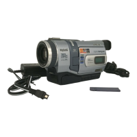
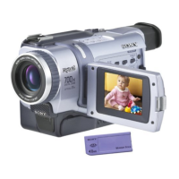
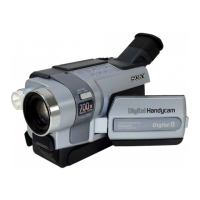
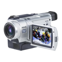
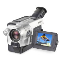
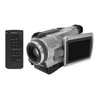
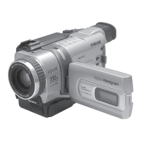
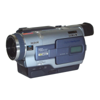
Lists included accessories and highlights functional differences between models.
Methods to prevent power shut-off during repairs and force eject cassette procedure.
Explains function, display codes, and how to access service mode.
Lists error codes, symptoms, and their corresponding corrections.
Highlights key features and provides initial setup instructions.
Explains manual usage, care precautions, battery installation, and charging.
Covers connecting to power and setting date/time for initial use.
Step-by-step guide to recording, and using playback review features.
How to adjust LCD panel angle/brightness and viewfinder settings.
Instructions on using zoom, digital zoom, and mirror mode.
Explains recording indicators and how to shoot backlit or in dark conditions.
How to use the self-timer for recording still images or video.
Functions to review and locate recorded content efficiently.
Step-by-step playback guide and how to manage screen indicators.
Explanation of data code and connecting for TV playback.
How to play back at slow speed, frame-by-frame, and search recorded scenes.
How to record still images on tape and use the self-timer.
How to record in wide mode and use fader effects for professional look.
How to apply various picture and digital effects to recordings.
How to adjust LCD panel angle/brightness and viewfinder settings.
Using zoom, digital zoom, and basic recording settings.
How to use automatic exposure modes and manual exposure adjustments.
How to manually focus and set up interval recording.
How to create stop-motion effects and add text titles to recordings.
How to apply effects during playback and enlarge recorded images.
How to use ZERO SET MEMORY, DATE SEARCH, and PHOTO SEARCH.
How to dub tapes and perform digital program editing for tapes.
Setting up VCR for editing and procedures for erasing programs.
Steps for digital editing with i.LINK and VCR synchronization adjustment.
How to create, set, and erase programs for digital editing.
How to dub onto Memory Stick and capture analog video via i.LINK.
How to record external sources and perform insert editing on tapes.
How to connect via USB and recommended PC specifications.
Steps to view recorded tape images on a computer using USB.
Instructions for installing the USB driver for computer connectivity.
How to view tape images on a Macintosh computer using USB.
How to capture images and customize camcorder menu settings.
Explains how to navigate and change various camcorder menu settings.
Provides detailed descriptions of various menu items and their functions.
Introduction to Memory Stick, file formats, and how to record still images.
How to select quality for still images and size for moving pictures.
How to record still images using self-timer and record continuously.
How to superimpose still images from Memory Stick onto moving pictures and record them.
How to record superimposed images and transfer moving images as stills.
How to record moving images from tape and use PHOTO SAVE to copy stills.
How to record moving pictures from tape and edit programs on Memory Stick.
How to perform digital editing on Memory Stick and manage programs.
How to play back still images and stop the playback mode.
How to play back still images and use index screen and moving picture playback.
How to view Memory Stick images on a computer using USB connection.
Steps to install the USB driver for computer connectivity.
How to view Memory Stick images on a Macintosh computer via USB.
Instructions for installing the USB driver for Macintosh computers.
How to copy still images from tape to Memory Stick using PHOTO SAVE.
How to enlarge and pan still images from Memory Stick.
How to protect images from deletion and how to delete images.
How to delete all images and mark images for printing.
How to use an optional printer to print images from Memory Stick.
Common recording and playback problems and their solutions.
Troubleshooting common Memory Stick functions and errors.
Explains warning indicators and messages displayed by the camcorder.
Overview of the Digital8 system, cassette compatibility, and playback.
Details on InfoLITHIUM battery technology, charging, and usage.
Explanation of i.LINK interface, standard, and required cables.
Details on i.LINK functions, cables, and using the camcorder internationally.
How to set the camcorder clock for different time zones using WORLD TIME.
Handling moisture condensation, charging the internal battery, and operating precautions.
Guidelines for handling tapes and general camcorder care.
Tips for cleaning lenses, body, and proper battery pack handling and storage.
Specific notes for dry batteries, including leakage precautions.
Identifies external parts, controls, and remote commander functions.
Explains various indicators displayed on the LCD screen and viewfinder.
Overview of disassembly process and detailed steps for major sections.
Steps for removing the LCD unit, PD-160 board, and back light assembly.
Steps for removing the front panel and SI-032 board, including microphone components.
Procedure for removing the right cabinet section, including switch blocks and harnesses.
Steps for disassembling the lens section and CD-357 board, including iris assembly.
Procedure for removing the EVF section and LB-076 board, including LCD and illuminator.
Steps for removing battery components, Memory Stick connector, and switch blocks.
Procedure for removing the left cabinet, CS frame, and SS-1380 switch block.
Steps for removing the VC-276 board and the mechanism deck.
Steps to set and exit the forced VTR power ON mode for service.
Steps to set and exit the forced camera power ON mode for service.
Steps for removing the CF-2500 and FK-2500 control switch blocks.
Procedure for removing the hinge assembly and related components.
Diagram showing the location of major circuit boards within the camcorder.
Diagram showing the location of various flexible boards.
High-level block diagram showing system interconnections.
Detailed block diagram of VC-276 board and its connections.
Block diagram illustrating the VC-276 board's relationship with other components.
Block diagram detailing the M2000 Mechanism Deck and VC-276 board connections.
Block diagram specific to DCR-TRV340, showing VC-272 board and PD-160 board connections.
Diagram showing the power supply distribution for the VC-276 board.
Diagram illustrating power distribution from VC-276 to other boards like LB-076.
Diagram showing power distribution to PD-160 and SI-032 boards.
Schematic diagram showing the overall frame connectivity.
Second part of the frame schematic diagram, showing detailed connections.
Explains measurement conditions, capacitor types, and schematic symbols.
Printed wiring board and schematic for the CD-357 CCD imager.
Printed wiring board and schematic for the LB-076 EVF and back light.
Printed wiring board for the SI-032 board (Steady Shot, Laser Link).
Printed wiring diagram for the FP-411 flexible board.
Schematic diagram for the SI-032 board (Steady Shot, Laser Link).
Schematic diagram for the FP-411 flexible board.
Printed wiring board for the PD-160 board components.
Printed wiring for PD-160 board (Side B) and FP-412 flexible board.
Schematic diagram for PD-160 board, covering CHA, Display Drive, Backlight.
Schematic diagram for PD-160 board, covering LCD Drive and TG.
Printed wiring and schematic for CF-2500 and FK-2500 switch blocks.
Printed wiring and schematic for various flexible boards.
Printed wiring and schematic for the FP-410 flexible board.
Table listing adjustments needed after replacing specific parts or boards.
Steps to initialize various page data settings for camera and mechanism.
Lists required service tools and initial setup for camera adjustments.
Adjusting lens iris position, AMP gain, and offset.
Automatic adjustment of inner focus lens flange back using minipattern box.
Specifies switch settings and subjects required for adjustments.
Detailed procedures for initializing D, A, B, C, 1C, 1F page data.
Table of addresses and initial values for D page data.
Table of addresses and initial values for A page data.
Steps to initialize B and 1B page data, including loader inhibit mode.
Table of addresses and initial values for B page data.
Table of addresses and initial values for 1B page data.
Steps to initialize 8, C, and 1C page data, including modification methods.
Table of addresses and initial values for C page data.
Continuation of addresses and initial values for C page data.
Table of addresses and initial values for 8 page data.
Table of addresses and initial values for 1C page data.
Steps to initialize E, F, 1F page data, including modification methods.
Table of addresses and initial values for F page data.
Table of addresses and initial values for E page data.
Table of addresses and initial values for 1F page data.
Adjusting lens iris position, AMP gain, and offset.
Automatic adjustment of inner focus lens flange back using minipattern box.
Adjustment of flange back using chart and distant subject.
Procedure to check the flange back adjustment after calibration.
Aligning the lens optical axis with the CCD imager for optimal focus.
Setting the picture frame for color reproduction adjustment.
Adjusting color separation matrix for proper color reproduction.
Inputting white balance reference and normal light value coefficient.
Correcting the white balance for proper LCD screen reproduction.
Checking white balance under indoor, outdoor, and LV conditions.
Checking steady shot function and angular velocity sensors.
Setting VCO free-run frequency to prevent EVF screen blur.
Setting uniformity improvement signal for LCD screen.
Setting RGB driver range for LCD screen.
Setting dynamic range of LCD driver to appropriate level.
Setting VIDEO signal level for LCD screen.
Setting video signal center level of LCD panel.
Setting DC bias of common electrode drive signal of LCD.
Correcting the white balance for proper LCD screen reproduction.
Operating procedures for Hi8/Standard 8 mode without cassette.
Procedure for checking and adjusting the tape path.
Procedures for entering record/playback modes without cassette.
Checking the tape path signal and RF waveform.
Lists required measuring instruments for video section adjustments.
Setting clock frequency for synchronization.
Setting the Y signal output level for S VIDEO jack.
Setting the Chroma signal output level for S VIDEO jack.
Checking sync and burst signal levels for VIDEO OUT.
Setting Y/C signal output level for Hi8/Standard8 playback.
Adjusting clock generator pull-in range for Hi8/Standard8 playback.
Sets BPF passing frequency for AFM signal separation.
Adjusting 1.5MHz and 1.7MHz audio FM signal deviation.
Checking playback signal level for Digital8 audio.
Checking audio level across different frequencies.
Checking audio distortion level.
Checking audio noise level.
Checking audio channel separation.
How to use the adjustment remote commander for changing coefficients.
Recommendations to prevent data loss and ensure correct adjustments.
How to process data and use the conversion table for adjustments.
How to set test modes and interpret emergence memory addresses.
Table of EMG codes corresponding to specific error types.
Explanation of MSW codes related to mechanism positions.
How to discriminate bit values using the adjustment remote commander.
Discriminating switch states based on bit values for DCR-TRV240/340.
Discriminating switch states for AUDIO/VIDEO, S VIDEO, MIC, HEADPHONES jacks.
Discriminating pressed keys based on display data.
Checking user initial power on date and condensation occurrence date.
Checking drum rotation time and other usage data.
Displays past self-diagnosis codes and refers to the function details.
Exploded view of the camcorder's overall section with part numbers.
Exploded view of the left cabinet section parts.
Exploded view of the second part of the left cabinet section.
Exploded view of the lens and EVF sections with part numbers.
Exploded view of the right cabinet section parts.
Exploded view of the LCD section components.
Exploded view of the cassette compartment and drum assembly.
Exploded view of the mechanical chassis block assembly.
Second exploded view of the mechanical chassis block assembly.
List of electrical components for the CD-357 board.
List of electrical components for the LB-076 board.
List of electrical components for the PD-160 board.
List of electrical components for the SI-032 board.
List of electrical components for the VC-276 board.
List of accessories with part numbers and remarks.
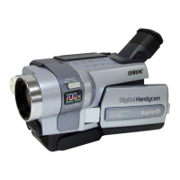
| Digital zoom | 700 x |
|---|---|
| Optical zoom | 25 x |
| Image stabilizer | Yes |
| Focal length range | 2.4 - 60 mm |
| Sensor type | CCD |
| Total megapixels | 0.8 MP |
| Optical sensor size | 1/6 \ |
| Display diagonal | 2.5 \ |
| Minimum illumination | 4 lx |
| Depth | 101 mm |
|---|---|
| Width | 85 mm |
| Height | 206 mm |