Do you have a question about the Sony DCR-TRV145E DCR-TRV147E DCR-TRV245E and is the answer not in the manual?
Details of changes made to the service manual over different versions.
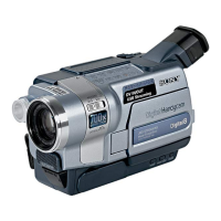
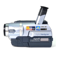
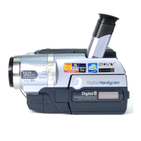
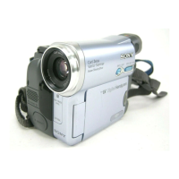
Technical details of the video camera recorder system, including recording format and playback time.
Details about the LCD screen, including size, resolution, and dot number.
Technical specifications for the AC power adaptor, including power requirements and output.
Specifications for the rechargeable battery pack, including voltage, capacity, and dimensions.
List of items included with the product package.
Comparison of functions across different models of the device.
Critical warning about components identified for safe operation and replacement procedures.
Steps for performing safety checks after repair before releasing the unit to the customer.
Important precautions regarding handling of flat cables, flexible boards, and connectors during repair.
Method to prevent power shut-off when using a regulated power supply during repairs.
Step-by-step guide on how to manually eject a cassette when the unit fails to eject.
Method to determine the type of LCD module installed by measuring resistor values.
Explanation of the self-diagnosis function and its two display modes: self-diagnosis and service mode.
Description of the 4-digit self-diagnosis display indicating repair status, error block, and detailed code.
Instructions on how to access and navigate the service mode display for self-diagnosis codes.
Comprehensive table listing self-diagnosis codes, symptoms, and corresponding corrections.
Diagram illustrating the connection of various external equipment for testing and operation.
Step-by-step instructions for disassembling the video light unit.
Procedure for removing and accessing the PD-180 board.
Instructions for disassembling the LCD module.
Steps for removing the control switch block (PR-3000).
Procedure for disassembling the VF Lens (B) assembly.
Instructions for disassembling the LB-090 board.
Steps for disassembling the cabinet (L) assembly.
Procedure for disassembling the F Panel block assembly.
Instructions for disassembling the SI-035 board.
Steps for disassembling the front ring assembly.
Procedure for disassembling the cabinet (R) block assembly.
Instructions for disassembling the control switch block (CF-3000).
Steps for disassembling the hinge assembly.
Instructions for disassembling the control switch block (FK-3000).
Steps for disassembling the EVF block assembly.
Procedure for disassembling the battery panel block assembly.
Instructions for disassembling the control switch block (SS-3000).
Steps for disassembling the lens block assembly.
Procedure for disassembling the FP-577 flexible board.
Instructions for disassembling the cabinet (L) section.
Steps for removing the VC-304 board.
Procedure for disassembling the mechanism deck block.
Diagram showing the location of various circuit boards within the device.
Diagram indicating the positions of flexible boards within the device.
Guidance on attaching harnesses and tape for the cabinet (R) block assembly.
Instructions for correctly installing the prism sheet and illuminator.
Detailed block diagrams illustrating the overall system architecture of the device.
Block diagrams showing the power distribution and circuitry within the device.
Schematic diagrams for the main frame of the device.
Detailed schematic diagrams for the VC-304 board, covering various functional blocks.
Schematic diagrams for the PD-180 board, detailing RGB drive and backlight functions.
Schematic diagrams for the LB-090 board, related to EVF and EVF backlight.
Schematic diagrams for the SI-035 board, covering Steadyshot and microphone functions.
Schematic diagrams for various flexible boards, including LS-057 and FP series.
Schematic diagrams for the control switch blocks (CF-3000, FK-3000, SS-3000, PR-3000).
Printed wiring diagram for the CD-418 board (CCD Imager).
Printed wiring diagrams for the VC-304 board, Side A and Side B.
Printed wiring diagrams for the PD-180 board, Side A and Side B.
Printed wiring diagrams for the LB-090 board, Side A and Side B.
Printed wiring diagrams for the SI-035 board, Side A and Side B.
Printed wiring diagrams for various flexible boards including LS-057 and FP series.
Illustrations of various waveforms measured from the CD-418 board.
Illustrations of various waveforms measured from the VC-304 board (1/4).
Illustrations of various waveforms measured from the VC-304 board (2/4).
Illustrations of various waveforms measured from the VC-304 board (3/4).
Illustrations of various waveforms measured from the VC-304 board (4/4).
Illustrations of various waveforms measured from the PD-180 board (1/2).
Illustrations of various waveforms measured from the PD-180 board (2/2).
Diagram showing the location of components mounted on the VC-304 board (Side A).
Diagrams showing component locations on PD-180 board (Side A and Side B).
Diagrams showing component locations on SI-035 board (Side A and Side B).
Illustrations of major assemblies with numbered parts for repair reference.
List of electrical components with part numbers, descriptions, and locations for various boards.
Detailed list of all accessories supplied with the product, including model numbers.
List of operating instructions provided for various regions and languages.