EasyManua.ls Logo

Sony DCR-TRV350 User Manual

Sony DCR-TRV350
49 pages
To Next Page IconTo Next Page
Page #1 background imageLoading...
Page #1 background image
SERVICE MANUAL
M2000 MECHANISM
LEVEL 3
Link
PRINTED WIRING BOARDS REPAIR PARTS LISTSCHEMATIC DIAGRAMS
Link
Revision History
Revision History
Ver 1.0 2002. 12
The information that is not described in this Service Manual is described
in the LEVEL 2 Service Manual.
When repairing, use this manual together with LEVEL 2 Service Manual.
•For ADJUSTMENTS (SENCTION 6), refer to SERVICE MANUAL, ADJ (987621851.pdf).
•For INSTRUCTION MANUAL, refer to SERVICE MANUAL, LEVEL 1 (987621841.pdf).
Reference No. search on printed wiring boards is available.
DCR-TRV345E/TRV350/TRV351/TRV355E/TRV356E
RMT-814
DIGITAL VIDEO CAMERA RECORDER
Contents of LEVEL 2 Service Manual
1. SERVICE NOTE
2. DISASSEMBLY
3. BLOCK DIAGRAMS
4. PRINTED WIRING BOARDS AND
SCHEMATIC DIAGRAMS
5. REPAIR PARTS LIST
OVERALL
POWER
CD-418, PD-181, LB-083, SI-036,
LS-057 BOARD,
FP-228, FP-299, FP-300, FP-301,
FP-302, FP-575, FP-577
FLEXIBLE
EXPLODED VIEWS
ELECTRICAL PARTS LIST
US Model
Canadian Model
DCR-TRV350
AEP Model
DCR-TRV345E/TRV355E
UK Model
DCR-TRV355E
East European Model
North European Model
DCR-TRV345E/TRV355E
E Model
DCR-TRV350/TRV351/TRV355E/TRV356E
Australian Model
DCR-TRV355E
Brazilian Model
DCR-TRV351
Chinese Model
DCR-TRV356E
Korea Model
DCR-TRV350
Tourist Model
DCR-TRV350/TRV355E
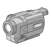
Photo: DCR-TRV350
Question and Answer IconNeed help?

Do you have a question about the Sony DCR-TRV350 and is the answer not in the manual?

Sony DCR-TRV350 Specifications

General IconGeneral
Optical Zoom20x
ViewfinderColor
MicrophoneStereo
USB InterfaceYes
FireWire InterfaceYes
Recording MediaMiniDV
Image Sensor1/4-inch CCD
LCD Screen Size2.5 inches
Battery TypeLithium-Ion

Summary

Service Manual Overview

Level 3 Service Manual Scope

Defines the technical level and scope of this service manual.

Schematic Diagrams

Core Signal Processing and Control Schematics

Schematics for A/D conversion, timing, video/audio DSP, DV processing, and lens control.

Power, Interface, and Memory Schematics

Schematics for power, USB/mode, MS interface, memory, and EVF drive.

Audio, Mic, and Servo Schematics

Schematics for audio, microphone, servo, and DC control circuits.

Printed Wiring Board Layouts

VC-305 Board Side A Layout

Physical layout of components on the VC-305 board, Side A.

VC-305 Board Side B Layout

Physical layout of components on the VC-305 board, Side B.

Waveform Analysis and Reference

Repair Parts List

Related product manuals