DSC-RX10_L2
2-6
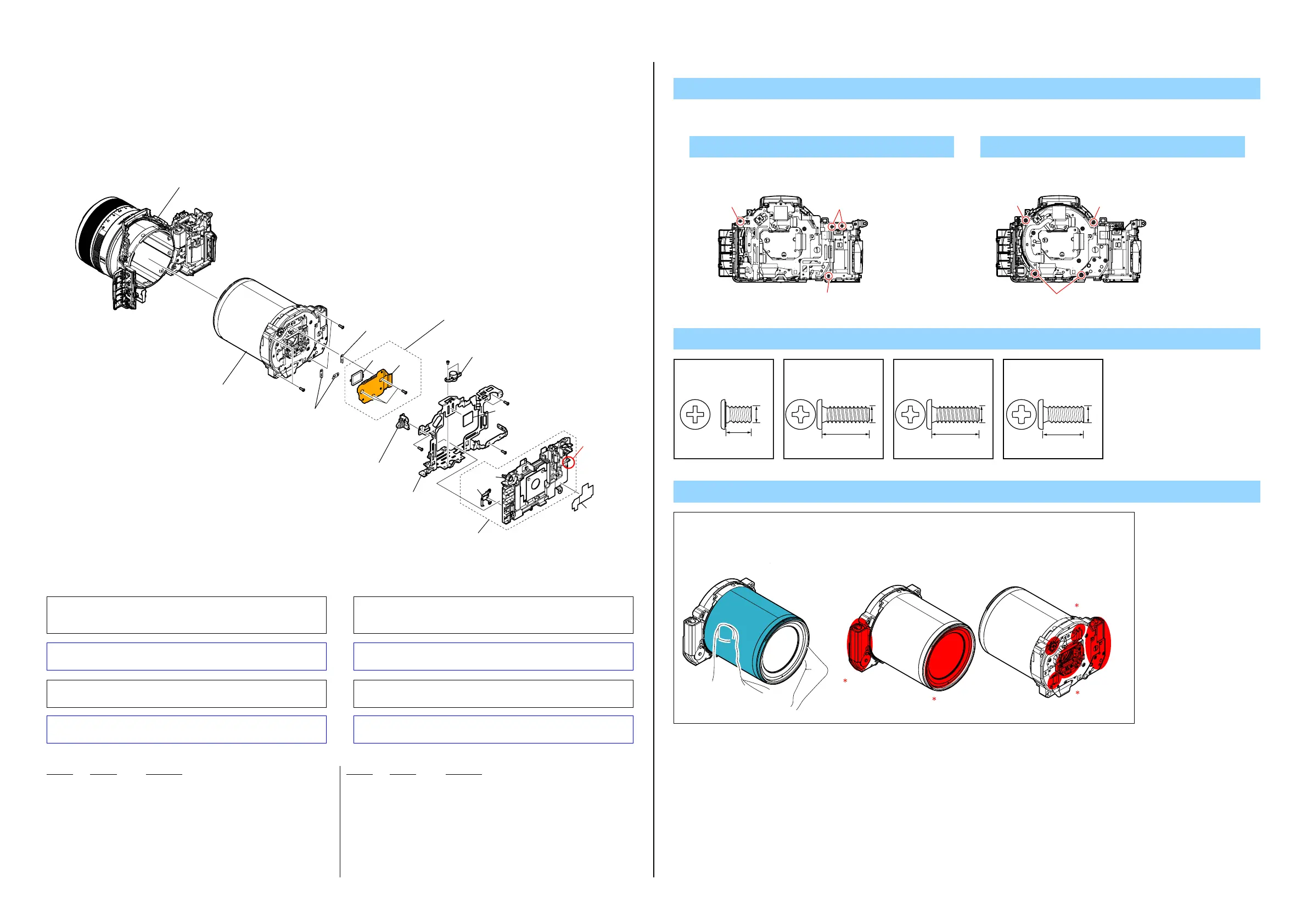
2-1-3. FRONT CABINET SECTION 1
ns : not supplied
Ref. No. Part No. Description
Ref. No. Part No. Description
101 A-1989-834-A CD-847 FLEXIBLE BOARD, COMPLETE (SERVICE)
(Note2, 3, 4)
102 4-470-413-01 RUBBER, SEAL
103 4-478-904-01 SCREW, TRIPOD
104 X-2588-287-1 STRAP EYELET ASSY (L)
* 105 4-478-903-01 FRAME, MAIN
106 A-1992-176-A HOLDER ASSY, SY (SERVICE)
107 Selection Parts SPACER PLATE
108 4-478-915-01 SHEET METAL, JK ELECTROSTATIC
109 4-528-669-01 SHEET (SY HOLDER)
#1 2-635-562-11 SCREW(M1.7)
#12 3-080-204-21 SCREW, TAPPING, P2
#155 3-080-204-31 SCREW, TAPPING, P2
#305 3-703-816-19 SCREW (M1.4X4.0), SPECIAL HEAD
1. Remove in numerical order (1to 4) in the left figure.
DISASSEMBLY
Lens Block Section
(See page 2-11)
(Note 1, 2)
Front Cabinet Section 2
(See page 2-7)
2
1
4
3
(Note 5)
(Claw)
101
102
103
106
105
108
109
104
107
107
#12
#305
#12
#12
#155
(including CP001
(CMOS imager))
(Note 2, 3, 4)
#155
#1
ns
ns
ns
2 #12 X 4 4 #155 X 4
Back View
#12
#12
#12
Back View
#155
#155
#155
Screw
#1: M1.7 X 2.5
(Black)
2-635-562-11
2.5
1.7
#12: M1.7 X 5.0 (Tapping)
(Black)
3-080-204-21
1.7
5.0
1.7
6.0
#155: M1.7 X 6.0 (Tapping)
(Black)
3-080-204-31
4.0
#305: M1.4 X 4.0
(Black)
3-703-816-19
1.4
SELECTION PARTS
Ref. No.107
These parts are provided for shift and tilt adjustment. Change the thickness
(t) according to result of adjustment
4-410-539-01 SPACER PLATE (A) (t=0.10)
4-410-539-21 SPACER PLATE (A) (t=0.12)
4-410-539-41 SPACER PLATE (A) (t=0.14)
4-410-539-61 SPACER PLATE (A) (t=0.16)
4-410-539-81 SPACER PLATE (A) (t=0.18)
4-410-540-01 SPACER PLATE (B) (t=0.20)
4-410-540-21 SPACER PLATE (B) (t=0.22)
4-410-540-41 SPACER PLATE (B) (t=0.24)
Note 2: When this part is removed, adjustment is required.
For the adjustment method, refer to “Adjustment items after
replacing parts” in the Note tab of the Adjust manual.
Note 2: この部品を取り外したときは調整が必要です。
調整方法についてはAdjust manual の NoteタブにあるAdjust-
ment items after replacing parts を参照してください。
Note 3: Refer to “1-3. NOTES ON REMOVING/INSTALLING THE
IMAGER BOARD (CD-847 FLEXIBLE BOARD)”.
Note 3: “1-3.イメージャ基板(CD-847フレキシブル基板)の取り外し/
取り付け時の注意”を参照してください。
Note 4: Be sure to read “Precautions for Replacement of Imager” on
page 6-1 of Level 3 when changing the imager.
Note 4: イメージャの交換時はLevel 3の6-1ページ、“イメージャ交換時
の注意”を必ずお読みください。
Note 5: Refer to “Assembly-4: Notes on assembling the SY Holder
Assy” when assembling.
Note 5: 組立時は“Assembly-4: Notes on assembling the SY Holder Assy”
を参照してください。
Note
Note 1 :
Hold the Lens Block at the
center of both sides.
Do not hold the following part.
Hold here.
NOTES ON HOLDING THE LENS BLOCK
Very weak
Very weak
Very weak
Very weak
4-410-540-61 SPACER PLATE (B) (t=0.26)
4-410-540-81 SPACER PLATE (B) (t=0.28)
4-437-388-01 SPACER PLATE C (t=0.30)
4-437-388-21 SPACER PLATE C (t=0.32)
4-437-388-41 SPACER PLATE C (t=0.34)
4-437-388-61 SPACER PLATE C (t=0.36)
4-437-388-81 SPACER PLATE C (t=0.38)
4-472-511-01 SPACER PLATE D (t=0.40)
4-472-511-21 SPACER PLATE D (t=0.42)
4-472-511-41 SPACER PLATE D (t=0.44)
4-472-511-61 SPACER PLATE D (t=0.46)
4-472-511-81 SPACER PLATE D (t=0.48)
4-472-512-01 SPACER PLATE E (t=0.50)
 Loading...