DSC-RX10_L2
2-5
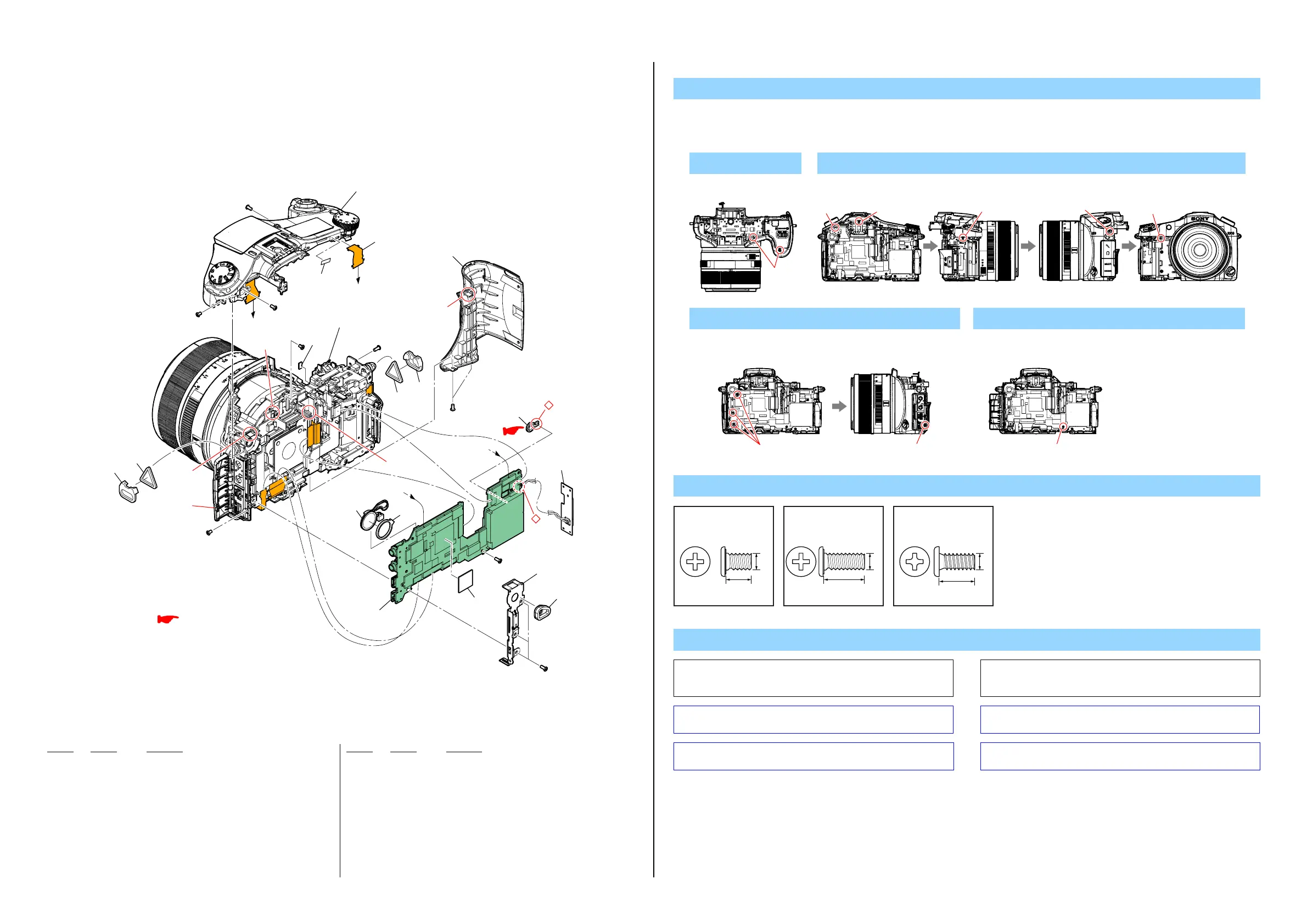
2-1-2. MAIN BOARD SECTION
Ref. No. Part No. Description
Ref. No. Part No. Description
51 4-478-899-01 GRIP (FRONT)
52 A-1973-588-A SY-1027 BOARD, COMPLETE (SERVICE) (Note 1)
* 53 4-484-165-01 SHEET, IC RADIATION
* 54 4-478-905-01 FRAME, JK
55 4-480-645-01 SPEAKER, CUSHION
56 1-889-134-11 CN-1026 FLEXIBLE BOARD
57 4-488-783-01 FRAME, CUSHION (JK)
58 4-489-532-01 EYELET TRIANGL (779)
59 4-487-875-01 HOLDER, EYELET TRIANGLE (779)
60 4-488-193-01 SHEET (VF), ADHESIVE
61 4-532-502-01 SPACER (CABINET UPPER)
ANT901 A-1989-833-A NFC BLOCK ASSY (SERVICE) (Note 2)
BT1000 1-756-813-11 LITHIUM RECHARGEABLE BATTERY
SP901 1-826-837-91 SPEAKER (1.3CM) (Note 3)
#1 2-635-562-11 SCREW (M1.7)
#2 2-635-562-31 SCREW (M1.7)
#5 3-080-204-01 SCREW, TAPPING, P2
1. Remove in numerical order (1to 4) in the left figure.
2. The meaning of the symbol in left figure is as follows. Be careful when you remove it.
◇: Solder
DISASSEMBLY
1 #5 X 2
#5
Bottom View
2 #5 X 1 → #1 X 1 → #2 X 1 → #1 X 1 → #1 X 5
#1
#5
#5
#2
#1
Back View Left View Right View Front View
Screw
#1: M1.7 X 2.5
(Black)
2-635-562-11
2.5
1.7
#2: M1.7 X 4.0
(Black)
2-635-562-31
4.0
1.7
#5: M1.7 X 3.5 (Tapping)
(Black)
3-080-204-01
3.5
1.7
A
B
B
A
(Claw)
(Claw)
(Claw)
(Claw)
57
56
53
55
58
58
59
59
60
52
51
61
54
#2
#2
BT1000
ANT901
(Note 2)
SP901
(Note 3)
#2
#1
#1
#1
#5
#5
#5
3
3
4
1
Upper Cabinet Section
(See page 2-8)
Front Cabinet Section 1
(See page 2-6)
: BT1000 (LITHIUM BATTERY)
Board on the mount position.
(See page 6-37 of Level 3)
(Note 1)
3 #2 X 3 → Open the USB lid (3) → #1 X 1
#2
#1
Back View Right View
Note
Note 1: When this part is removed, adjustment is required.
For the adjustment method, refer to “Adjustment items after
replacing parts” in the Note tab of the Adjust manual.
Note 1:
この部品を取り外したときは調整が必要です。
調整方法についてはAdjust manual の Noteタブにある
Adjustment items after replacing parts を参照してください。
Note 2: Refer to “Assembly-1: Notes on installing the NFC Block Assy”
when assembling.
Note 2: 組立時は“Assembly-1: Notes on installing the NFC Block Assy”
を参照してください。
Note 3: Refer to “Assembly-2: Notes on installing the Speaker” when
assembling.
Note 3:
組立時は“Assembly-2: Notes on installing the Speaker” を
参照してください。
4 #2 X 1
#2
Back View
 Loading...