DSX-A50BT
28
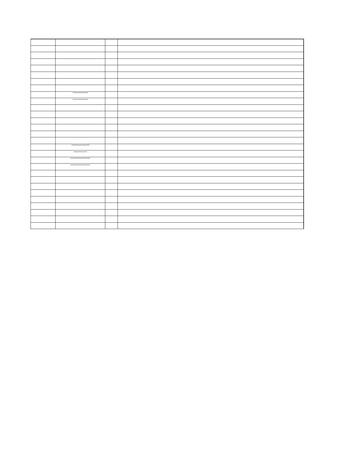
Pin No. Pin Name I/O Description
67 to 71 NC - Not used
72 AMP_REM O Amplifi er remote output on/off control signal output terminal “H”: output on
73 SYS_EN O System power on/off control signal output to the DC/DC converter “H”: power on
74 AUDIO_EN O Power supply on/off control signal output terminal for audio section “H”: power on
75 BT_TX (A50) O Serial data output to the Bluetooth section
76 BT_RX (A50) I Serial data input from the Bluetooth section
77, 78 NC - Not used
79 RE_IN0
I Jog dial pulse signal input from the rotary encoder (A phase input) (for volume)
80 RE_IN1
I Jog dial pulse signal input from the rotary encoder (B phase input) (for volume)
81 BT_MIC_ON (A50) O Power supply on/off control signal output terminal for microphone signal “H”: power on
82 BT_RTS (A50) O Return to send signal output to the Bluetooth section
83 BT_CTS (A50) I Clear to send signal input from the Bluetooth section
84 BT_RESET (A50) O Reset signal output to the Bluetooth section “L”: reset
85 BT_POWER (A50) O Power supply on/off control signal output to the Bluetooth section “H”: power on
86 NC - Not used
87 SYS_ON
O System on/off control signal output terminal “L”: system on
88 RCIN1
I Rotary commander shift key input terminal
89 KEYACK0
I Key acknowledge detection signal input terminal for the rotary commander key entry
90 KEYACK1
I Key acknowledge detection signal input terminal for the front panel key entry
91 NC - Not used
92, 93 KEYIN1, KEYIN0 I Front panel key signal input terminal
94 AVSS - Ground terminal (for A/D converter)
95 RC_IN0 I Rotary commander key input terminal
96 AVRH - Reference voltage terminal (+3.3V) (for A/D converter)
97 AVDD - Power supply terminal (+3.3V) (for A/D converter)
98 LCD_CE O Chip enable signal output to the liquid crystal display driver
99 LCD_SO O Serial data output to the liquid crystal display driver
100 LCD_CLK O Serial data transfer clock signal output to the liquid crystal display driver
 Loading...