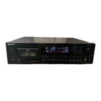
DTC-|(NxrEs
SAFETY.RE
LATED
COMPONENT WARNING! !
COMPONENTS
IDENTIFIED BY SHADING AND
MARK
7\
oru
rxe
scHEMATrc DIAGRAMs AND
rN
THE
PARTS
LIST ARE
CRITICAL
TO SAFE
OPERATION.
REPLACE THESE COMPONENTS WITH SONY PARTS
WHOSE PART
NUMBERS APPEAR
AS
SHOWN
IN
THIS
MANUAL
OR IN SUPPLEMENTS PUBLISHED BY SONY.
TABLE
OF
CONTENTS
Description
Page
Outline
3
BlockDiagram...
7
Disassembly
13
Adjustments
LI
Mechanical
Adjustment
L7
ElectricalAdjustment
.....
....20
Diagrams.
32
MountingDiagram
(MD
Servo& Digital Block).
....33
Schematic
Diagram
(MD
Servo
Block).
37
Mounting Diagram
(Power
Block).
43
SehematieDiagram(PowerBlock).
......
44
Schematic
Diagram
(Digital
Block) . 47
Mounting
Diagram
(Anatog
& Microcomputer
Block)
.
Schematie Diagnam
(Analog
&
Microcomputer
Block).
Exploded Views
and
Parts
List 69
Eleetrical Parts
List
79
Flexible Circuit Board Repairing
r
Keep the temperature of the
soldering iron around 27 0"
C
during repairing.
.
Do not touch the
soldering iron on
the
same conductor of
the circuit board
(within
3
times).
o
Be careful not to
apply
force
on
the
conductor
when
soldering or unsoldering.
Notes
on chip
component
replacement
.
Never
reuse a disconnected
chip
component.
.
Notice that the minus side
of a tantalum capacitor may be
damaged
by
heat.
Title
Section 1.
Seetion 2.
Seetion
3.
Section 4.
4-1.
4-2.
Section
5.
5-1.
5_2.
5-3.
5-4.
5-4.
5-5.
5-6.
Section
6.
Seetion
?.
-2-
 Loading...