Do you have a question about the Sony DVCAM DSR-11 and is the answer not in the manual?
Details recording format, video/audio quantification, standardization frequencies, cassette compatibility, and recording time.
Lists video, audio, and control inputs/outputs with signal levels and impedance.
Covers power consumption, operating temperature, and storage temperature.
Highlights components critical to safe operation and requires replacement with specific Sony parts.
Outlines essential safety checks to perform before releasing the unit after repairs.
Provides crucial advice for handling cables and connectors during repairs to prevent damage.
Explains the self-diagnosis function and its two display modes: self-diagnosis and service mode.
Describes the 5-character self-diagnosis display format indicating repair status, block, and detailed code.
Details how to enter Service Mode to view past self-diagnosis codes.
Lists self-diagnosis codes, symptoms, and suggested corrections for troubleshooting.
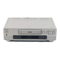
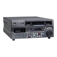
Highlights core features like DVCAM format, high picture quality, wide track pitch, PCM audio, and DV compatibility.
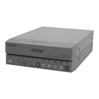
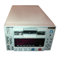
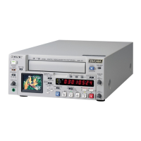
Identifies and explains the function of front panel buttons, selectors, and indicators.
Details the function of rear panel connectors like LANC, DV I/O, and switches like NTSC/PAL select.
Explains the operation of the remote commander buttons for unit control.
Step-by-step instructions for removing the upper case of the unit.
Procedure for removing the front panel assembly.
Instructions for disassembling the VD-031 circuit board.
Steps for removing the DC/DC converter unit.
Instructions for disassembling the HD-024 circuit board.
Procedure for removing the mechanism deck assembly.
Instructions for disassembling the JC-20 circuit board.
Steps for disassembling the RP-234 circuit board.
Diagram showing the location of major circuit boards within the unit.
Presents the first overall system block diagram.
Presents the second overall system block diagram.
Presents the third overall system block diagram.
Presents the fourth overall system block diagram.
Illustrates the first power supply block diagram.
Illustrates the second power supply block diagram.
Illustrates the third power supply block diagram.
Illustrates the fourth power supply block diagram.
Provides guidelines for understanding printed wiring boards and schematic diagrams.
Shows the first part of the overall frame schematic diagram.
Shows the second part of the overall frame schematic diagram.
Detailed schematic diagrams for the RP-234 board.
Detailed schematic diagrams for the JC-20 board.
Detailed schematic diagrams for the VD-031 board.
Detailed schematic diagrams for the HD-024 board.
Schematic diagram for the MD-76 board.
Schematic diagram for the FR-175 board.
Schematic diagram for the JA-006 board.
Schematic diagram for the JD-002 board.
Schematic diagram for the DC-1492 board.
Illustrates key waveforms for the RP-234 board.
Illustrates key waveforms for the JC-20 board.
Illustrates key waveforms for the VD-031 board.
Illustrates key waveforms for the HD-024 board.
Diagram showing the location of parts on the RP-234 board (Side A and B).
Diagram showing the location of parts on the JC-20 board (Side A).
Diagram showing the location of parts on the HD-024 board (Side A).
Procedures for re-writing EVR data when replacing boards or EEPROM.
Table detailing adjustments required after replacing main parts.
Table detailing adjustments required after replacing boards or EEPROM.
Procedures for adjusting mechanical parts.
Lists essential tools required for service and adjustment procedures.
Information on using the Mode Selector II for mechanism control and connection.
Table outlining periodic maintenance checks based on operating hours.
Instructions for cleaning the rotary drum assembly and tape path system.
Procedures for checking and adjusting tape guides (1/8 and 2/7).
Disassembly and assembly procedures for various mechanical parts.
Flowchart outlining the sequence for tape path and height adjustments.
Procedure for checking and adjusting reel table height.
Procedure for checking and adjusting TG1/8 height.
Procedure for checking and adjusting TG2/7 height.
Procedure for checking and adjusting FWD/RVS positions.
Procedure for checking and adjusting electric tension regulators.
Procedure for checking and adjusting FWD/RVS back tension.
Steps for preparing adjustments and checking tape path using RF waveform.
Procedure for adjusting and checking track RF waveforms.
Procedure for checking track waveform amplitude differences.
Procedure for checking waveform peak consistency in CUE/REV modes.
Procedure for checking and adjusting tape curls on guides and pinch roller.
Procedure for checking waveform rising horizontally within 2 seconds after mode switching.
Details on entering Service Mode and operating the adjusting remote commander.
Explains how to convert hexadecimal data to decimal for adjustments.
Procedure for setting the test mode and managing emergency memory addresses.
Lists emergency codes for errors and MSW codes for mechanism positions.
Explains how to discriminate bit values using adjustment remote commander display data.
Procedure for checking and initializing record of use data, especially drum rotation time.
Lists required equipment and alignment tapes for video adjustments.
Procedures for checking S VIDEO and VIDEO input signals using an oscilloscope.
Details the alignment tapes required for various adjustments.
Specifications for all unit inputs and outputs.
Procedures for initializing, inputting, and modifying system control data.
Procedures for adjusting servo and RF system parameters.
Specific adjustment procedures for the JC-20 board.
Adjustment procedures for the VD-031 board, including decoder and Y/C separation.
Procedures for HUE adjustment in both NTSC and PAL modes.
Procedures for checking playback level, S/N ratio, and distortion.
Provides exploded views of major assemblies for parts identification.
Exploded view of the entire unit's overall assembly.
Exploded view and parts list for Chassis Assembly-1.
Exploded view and parts list for Chassis Assembly-2.
Exploded view and parts list for the mechanism deck drum assembly.
Exploded view and parts list for mechanism deck gear and arm components.
Exploded view and parts list for mechanism deck motor and MD board.
Exploded view and parts list for the mechanism deck cassette compartment.
List of electrical components for the DC/DC Converter Unit (DC-1492).
List of electrical components for the HD-024 board.
List of electrical components for the JC-20 board.
List of electrical components for JD-002, MD-76, and RP-234 boards.
List of electrical components for the VD-031 board.