DVP-CX985V
4949
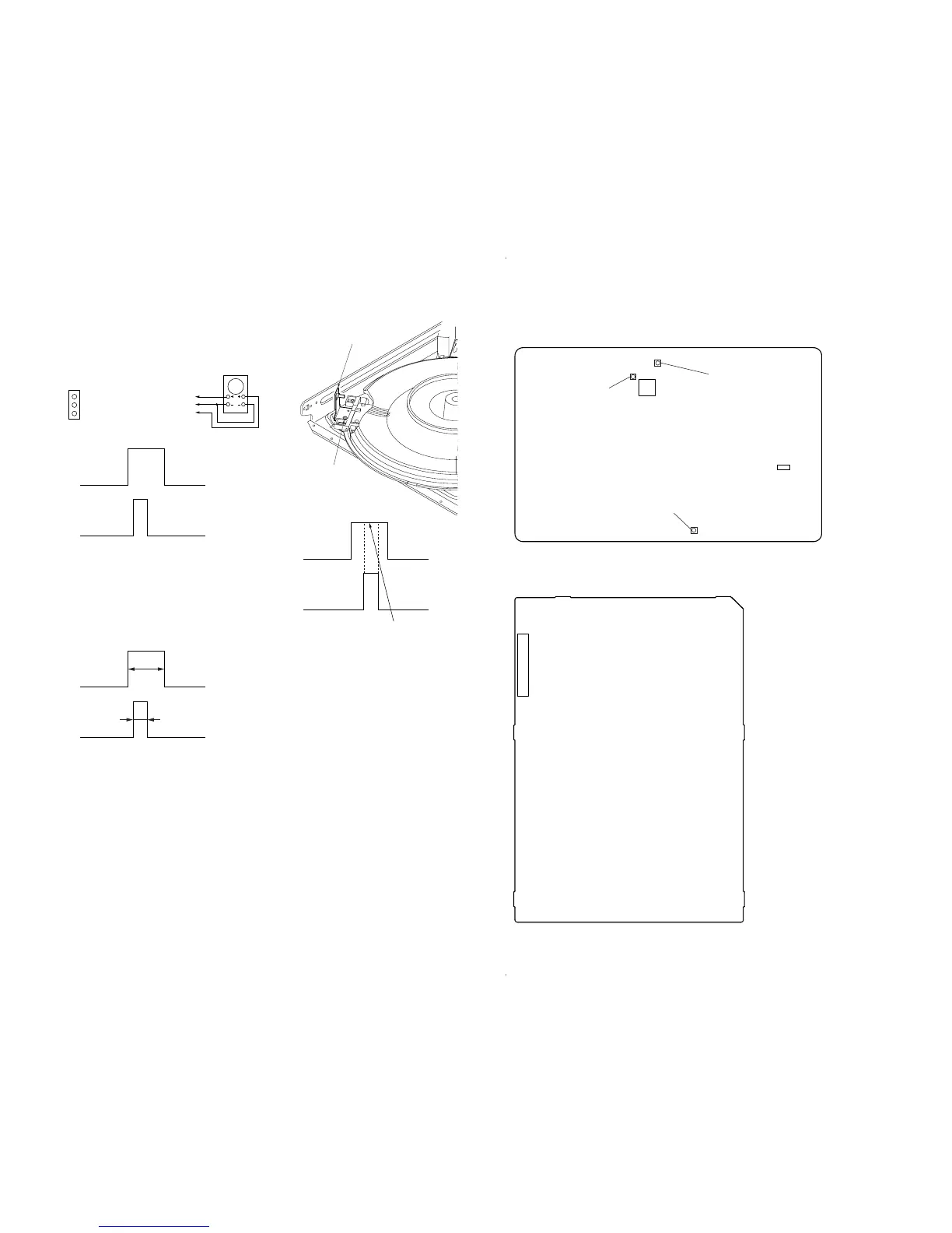
6-4. DISC DETECT SENSOR ADJUSTMENT
Be sure to perform this adjustment after sensor adjustment in ME-
CHANICAL ADJUSTMENT.
Connection:
Waveform:
1. Connect the oscilloscope to Pins 1, 2 and 3 of CN701 of
the MB board.
2. Check that no discs are loaded in the unit.
3. Perform from step 1 to step 5 in Pop Up Mechanism Adjust-
ment.
4. Press the [PAUSE] key, then the T.table starts to rotate in the
clockwise direction.
5. Rotate RV101 of MB board and adjust so that the H portion A
of DSENS_OUT waveform is twice the width of the H portion
B of HH_OUT waveform.
Adjustment Location: MB board
6. Loosen the fixing screw, move the mounting board (SENSOR),
and secure the mounting board (SENSOR) at the point the H
portion of the HH_OUT waveform comes the center of the H
portion of the DSENS_OUT waveform.
DSENS_OUT: Pin
3
GND: Pin
2
HH_OUT: Pin
1
oscilloscope
CH1 CH2
DSENS_OUT
GND
HH_OUT
MB board
CN701
DSENS_OUT
HH_OUT
CH1
CH2
DSENS_OUT
HH_OUT
CH1
CH2
A
A = 2
×
B
B
S tight, screw
(PTTWH 3
×
6)
D. sens (out) board
DSENS_OUT
HH_OUT
CH1
CH2
Should be at the center
Adjustment Location:
IC604
CN701
+
+
RV602
Progressive Video Output
Level Adjustment
RV101
Disc Detect
Sensor Adjustment
RV601
Video Level
Adjustment
+
13
1
CN201
13
– MB Board (Component Side) –
– POWER Board (Conductor Side) –



 To Next Page