46
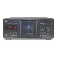
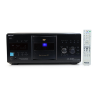
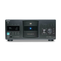
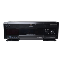
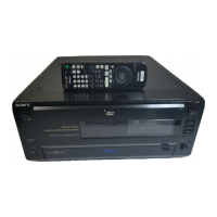
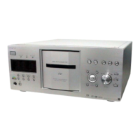
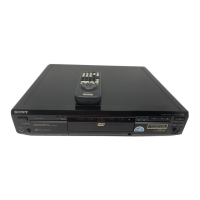
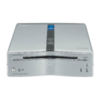
DVP-CX985V
SECTION 6
ELECTRICAL ADJUSTMENTS
This section describes procedures and instructions necessary for
adjusting electrical circuits in this unit.
Instruments required:
1) Color monitor TV
2) Oscilloscope 1 or 2 phenomena, band width over 100 MHz,
with delay mode
3) Frequency counter (over 8 digits)
4) Digital voltmeter
5) Standard commander (RM-DX700)
6) CD reference disc
YEDS-18 (3-702-101-01)
PATD-012 (4-225-203-01)
7) DVD reference disc
HLX-501 (J-6090-071-A) (dual layer) (NTSC)
HLX-503 (J-6090-069-A) (single layer) (NTSC)
HLX-504 (J-6090-088-A) (single layer) (NTSC)
HLX-505 (J-6090-089-A) (dual layer) (NTSC)
8) SACD reference disc
HLXA-509 (J-6090-090-A)
9) Extension Cable (J-6090-107-A)
6-1. AUTO SERVO ADJUSTMENT
After parts related to the servo circuit (RF amplifier (IC201), DSP
(IC301), motor driver (IC202), EEPROM (IC101) so on) are re-
placed, re-adjusting the servo circuit is necessary. Select “ALL” at
“DRIVE AUTO ADJUSTMENT” (Refer to page 27 in TEST
MODE) and adjust DVD-SL (single layer), CD and DVD-DL (dual
layer).
In making adjustment, refer to 5-5. Adjustment
Related Parts Arrangement.
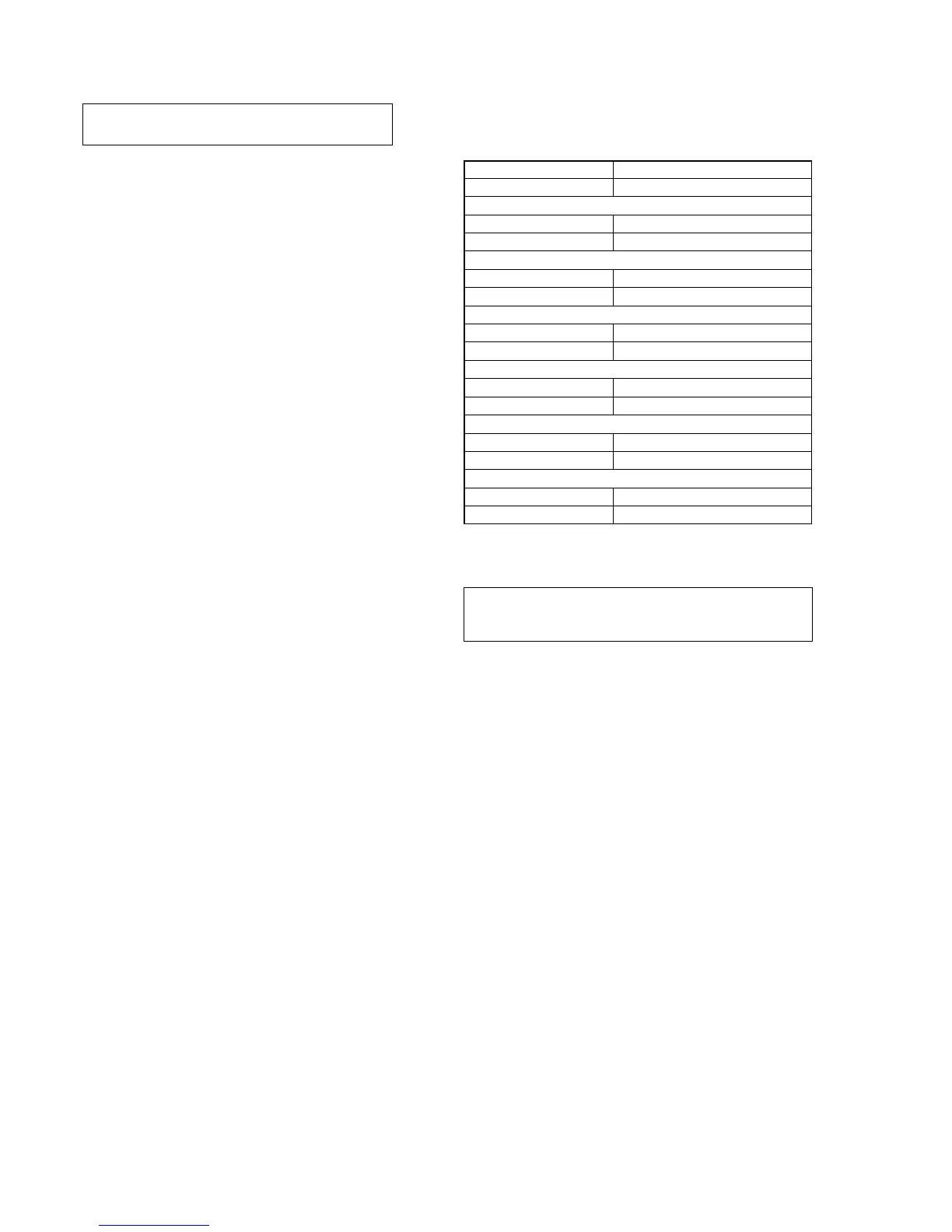
6-2. POWER SUPPLY CHECK
1. POWER Board
Checking method:
1) Confirm that each voltage satisfies the specification.
Note
Because the heatsink installed on the power supply board is a part of
the primary side, never touch it to avoid electrical shock.
Mode E-E
Instrument Digital voltmeter
EVER +3.3 V Check
Test point CN201 pin qa
Specification 3.5 ± 0.2 Vdc
SW +3.3 V Check
Test point CN201 pin 8
Specification 3.5 ± 0.2 Vdc
SW +5 V Check
Test point CN201 pin qs
Specification 5.0 ± 0.3 Vdc
SW +11 V Check
Test point CN201 pin 6, 7
Specification 11.0 ± 1.0 Vdc
EVER +11 V Check
Test point CN201 pin qd
Specification 11.0 ± 1.0 Vdc
EVER –11 V Check
Test point CN201 pin 2
Specification –11.0 ± 1.0 Vdc