Do you have a question about the Sony DVP-NS405 and is the answer not in the manual?
Details technical specifications for the DVD player.
Procedure to measure AC leakage current from exposed metal parts.
Highlights critical components for safe operation.
Instructions for safely removing a disc from the player.
Procedure for servicing the MB-103 board, including jig usage.
Important safety and operational precautions for the player.
Details on checking model name and understanding manual icons.
Lists types of discs incompatible with the player.
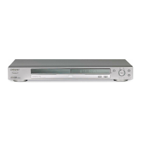
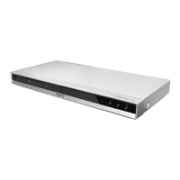
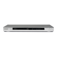
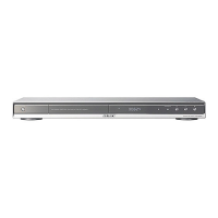
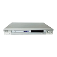
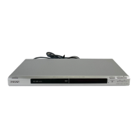
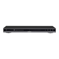
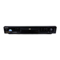
Identification of controls and indicators on the front panel.
Identification of input and output jacks on the rear panel.
Identification of buttons on the remote control.
Provides a brief overview of player setup and usage.
Instructions for connecting the player to a TV.
Steps for inserting and playing a disc.
Guide to connecting video cables to TV or other devices.
Guide to connecting audio cables to various systems.
Instructions for connecting the power cord.
Initial setup steps for language, aspect ratio, and audio.
How to resume playback from where a disc was stopped.
Methods for searching discs by scan, slow-motion, freeze frame.
Navigating DVD menus for titles, subtitles, and audio.
Using Program Play, Shuffle Play, Repeat Play, A-B Repeat Play.
Checking playing time, remaining time, and disc text.
Changing sound formats and audio signal output.
Enabling virtual surround sound effects.
Adjusting picture quality, angles, and subtitles.
Setting parental controls to restrict disc playback.
Using the remote to control basic TV functions.
Configuring player settings via the Setup Display.
Instructions for removing the upper case of the unit.
Procedure for removing the front panel assembly.
Steps to remove the loading mechanism assembly.
Procedure for removing the optical pickup device.
Disassembly steps involving the DC motor and MS-81 board.
Procedure for removing the ER-14R board.
Steps to remove the AV-61 board.
Procedure for removing the MB-103 board.
Steps for removing the IF-89 board.
Procedure for removing the switching regulator.
Illustrations showing internal views of the mechanism.
Diagram showing the location of various circuit boards.
High-level overview of the system's functional blocks.
Detailed diagram of the RF and Servo systems.
Diagram illustrating the signal processing path.
Diagram showing the system control functions.
Diagram illustrating the video signal processing.
Diagram illustrating the audio signal processing.
Diagram showing the interface control functions.
Diagram of the power supply system.
Continuation of the power supply system diagram.
Overall schematic diagram of the player's layout.
Notes common to wiring boards and schematic diagrams.
Illustrations of typical signal waveforms for testing.
Printed wiring board layout for the IF-89 board.
Schematic diagram for the MB-103 board, side A.
Schematic diagram for the MB-103 board, side B.
Schematic for DVD/CD RF AMP and Digital Servo.
Schematic for motor drive circuits.
Schematic for servo control circuits.
Schematic for AV decoder circuits.
Schematic for SDRAM memory circuits.
Schematic for system control circuits.
Schematic for audio DAC and PLL circuits.
Schematic diagram for the AV-61 board, part 1.
Schematic diagram for the AV-61 board, part 2.
Schematic diagram for the ER-14 AV AMP board.
Schematic diagram for the switching regulator.
Detailed pin functions for the system control IC.
Overview of how to use the test mode.
System control diagnosis menu and checks.
Explanation of test procedures and error codes.
Procedure for automatically adjusting drive mechanisms.
Manual control and adjustment of drive mechanisms.
Automatic adjustment of specific servo parameters.
Checking stored servo adjustment data in EEPROM.
Common issues and solutions encountered in test modes.
Checking various voltage outputs from the power supply.
Adjusting video output levels for NTSC standard.
Verifying component video output signals (Y, S-Y, S-C, B-Y, R-Y).
Layout of adjustment-related components on boards.
Exploded view of the player's main mechanical components.
Exploded view of the disc loading mechanism.
List of electrical components for the AV-61 board.
List of electrical components for ER-14, FL-126, IF-89 boards.
List of electrical components for the MB-103 board.
List of electrical components for the MS-81 board.
| Type | DVD Player |
|---|---|
| Supported Discs | DVD, CD, CD-R/RW |
| Progressive Scan | Yes |
| Width | 430 mm |
| Audio D/A Converter | 24-bit/192 kHz |
| Audio Formats Supported | Dolby Digital, DTS, MP3 |
| Output Video | Composite Video, S-Video |
| Video D/A Converter | 10 bit / 27 MHz |
| Output Audio | Analog Audio, Digital Audio (Coaxial, Optical) |
| Remote Control | Included |