Do you have a question about the Sony DVP-NS32 and is the answer not in the manual?
Procedures for testing AC leakage from exposed parts.
Important safety warnings and cautions for servicing.
Instructions for connecting the player and initial setup.
Steps for removing a disc when the unit is powered off.
Warnings about fire, shock hazard, placement, and liquid exposure.
Warning about permanent damage to TV screens from static images.
Detailed steps for connecting video output to TVs, projectors, or amplifiers.
Specifics for connecting progressive signals on compatible devices.
Instructions for connecting audio outputs (analog and digital).
Setting up playback restrictions for discs using Parental Control.
Configuring custom playback restrictions for discs.
Setting playback limitations based on age or content rating.
Configuring audio output based on playback and connection conditions.
Solutions for common playback, power, and picture issues.
Detailed technical specifications of the player.
Steps for removing the top cover of the unit.
Steps for disassembling the front panel.
Steps for removing the disc loading mechanism.
Steps for removing the optical pickup unit.
Important safety warning regarding the laser diode's sensitivity.
Steps for removing main circuit boards.
A comprehensive overview of the player's system architecture.
Detailed block diagram for system control and signal processing.
Block diagram detailing the RF and servo control systems.
Schematic details for the CPU, Servo-DSP, and AVDEC sections.
Schematic details for the drive motor control section.
Schematic details for the video signal processing.
Schematic details for the audio signal processing.
Schematic details for the power supply section.
Schematic diagram for the IF-124 interface board.
Schematic diagram for the ER-037 (Euro Out) board.
Schematic diagram for the power block.
Detailed description of pin functions for the main system control IC.
Remaining pin function details for the system control IC.
Standard procedures for measuring IOP.
How to access and interpret emergency history data.
Procedure for resetting player setup data.
Using the IF CON self-diagnostic mode.
Procedures for verifying and adjusting power supply voltages.
| Audio decoders | DTS |
|---|---|
| Frequency response CD | 2 - 20000 Hz |
| Audio dynamic range CD | 99 dB |
| Frequency response DVD | 2 - 44000 Hz |
| Audio dynamic range DVD | 103 dB |
| I/O ports | 1x Video out 1x SCART 1x Analog Stereo output Audio output(coaxial) |
| Dimensions (WxDxH) | 430 x 237.7 x 43 mm |
| Power requirements | 220–240 V, 50/60 Hz |
| Disc types supported | DVD+R, DVD+RW |
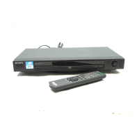
| Product color | Black |
| Operating temperature (T-T) | 5 - 35 °C |
| Operating relative humidity (H-H) | 25 - 80 % |
| Power consumption (standby) | 0.1 W |
| Power consumption (typical) | 11 W |
| Weight | 1950 g |
|---|