1. Charging light/Notification light
2. Front camera lens
3. Ear speaker
4. Proximity/Light sensor
5. Second microphone
6. Power key
7. Volume/Zoom key
8. Camera key
9. Main microphone/Speaker
10. Charger/USB cable port
11. Strap hole
12. Main Wi-Fi/Bluetooth antenna area
13. Main camera lens
14. Camera light
15. GPS antenna area
16. Headset jack*
17. Second Wi-Fi antenna area
18. Nano SIM/Memory card slot cover
19. NFC™ detection area
Your device supports headsets with a standard 3.5 mm 3-pin or 5-pin headphone plug. The
headset jack also supports 4-pin plugs as long as the headphone plug uses the CTIA
standard.
Protecting the Screen
At purchase, there are two sheets of plastic film on the front of your device. You can
peel off the outer sheet of film when you start using the device. It is not
recommended to peel off the second sheet of film, as it protects your screen from
damage and scratching.
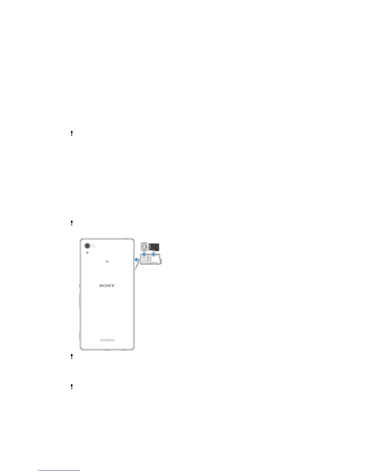
Assembly
Your device only supports nano SIM cards. The nano SIM card and the memory card share the
same holder but have separate slots. Make sure you don’t confuse the two.
To prevent data loss, be sure to turn off your device or unmount the memory card before you
drag out the holder to remove the nano SIM card or memory card.
To Insert the Nano SIM Card
If you insert the nano SIM card while the device is powered on, the device restarts
automatically. The nano SIM card and memory card share the same holder. If a memory card
is already inserted in the holder and the device is powered on, you must turn off the device or
unmount the memory card before removing the holder to insert the nano SIM card. You can
unmount the memory card under Settings by tapping Storage > Unmount SD card.
8
This is an Internet version of this publication. © Print only for private use.