EasyManua.ls Logo

Sony FDT-5BX5 User Manual

Sony FDT-5BX5
21 pages
To Next Page IconTo Next Page
Page #1 background imageLoading...
Page #1 background image
FDT-5BX5
SERVICE MANUAL
US Model
SPECIFICATIONS
TV standard
Color system
Channel coverage
Radio frequency
range
Antenna
Picture size
Speaker
EXT ANT (TV)
VIDEO IN
output
Power requirement
American TV standard
NTSC
VHF channel 2-13
UHF channel 14-69
FM:87.6-108MHz
AM:530-1,710kHz
VHF/UHF/FM:
telescopic antenna
AM:built-in
ferrite bar
antenna
5-inch
picture measured
diagonally
80mm (3 f/4 inches) dia.
minijack, impedance
75 ohms (for TV)
VIDEO:phono jack,
1 Vp-p. 75 ohms,
unbalanced, sync negative
AUDIO:phono jack,
-7.5
dBs,
input impedance
more than 47 kilohms.
EARPHONE: earphone
jack, impedance 8-300 ohms
13.5V
DC, See “Power
sources”. (page 4)
Power consumption
20W (135V.
1.48A)
AC
adaptor use
Dimensions
Approx.165 x 211
x
224 mm
(w/h/d)
(6
l/2
x 8
3/s
x 8
y/a
inches)
incl. projecting parts
Mass Approx.2.7kg (5 lb 15
oz)
Supplied accessory
AC power adaptor (ACE55) (1)
Design and specifications are subject to change
without notice.
FEATURES
. Equipped with a
5-inch
CRT Color TV.
*
FM/AM tuner is combined.
-
Built-in 80mm dia. speaker with MEGA BASS
sound.
*
VIDEO/AUDIO input jacks for use with a color
monitor for video equipment.
. The voltage synthesizer tuning system allows
for easy tuning.
COLOR TV-AM/FM TUNER
SONY@
Question and Answer IconNeed help?

Do you have a question about the Sony FDT-5BX5 and is the answer not in the manual?

Sony FDT-5BX5 Specifications

General IconGeneral
TypeTV Tuner
ModelFDT-5BX5
ManufacturerSony
TV SystemNTSC
Tuner TypeAnalog
Power SourceAC
InputRF
OutputHeadphone Jack
Supported Resolutions480i
Power SupplyAC 120V

Summary

Anode Cap Removal Procedure

Anode Cap Removal Steps

Procedure for safely removing the anode cap to prevent electrical shocks.

Safety Check-out Procedures

Leakage Test and Grounding

Methods for testing AC leakage and ensuring a proper earth ground connection.

Section 1 General

Section 2 Disassembly

Rear Cabinet Disassembly

Procedure for disassembling the rear cabinet.

D Board Disassembly

Procedure for disassembling and accessing the D Board.

Dial Assembly Disassembly

Procedure for disassembling the dial assembly.

Cathode-ray Tube Removal

Procedure for handling and removing the cathode-ray tube.

Dial Pointer Setting

Instructions for setting the dial pointer correctly.

Section 3 Safety Related Adjustments

B+ Max Voltage Confirmation

Procedure for confirming and adjusting the B+ MAX voltage.

Hold-Down Circuit Confirmation

Procedure for confirming the hold-down circuit functionality.

Section 4 Diagrams

Semiconductor Lead Layouts

Visual guide to semiconductor lead pinouts and configurations.

Block Diagram

Overview of the unit's functional blocks and signal flow.

Circuit Boards Location

Diagram showing the physical location of internal circuit boards.

Printed Wiring Boards A/R Boards

Printed wiring board layouts for A/R boards.

Schematic Diagram A/R Boards

Schematic diagrams for the A/R circuit boards.

Schematic Diagram C/D/F Boards

Schematic diagrams for the C/D/F circuit boards.

Accessories & Packing Materials

Hardware List

List of screws, pins, and other hardware components.

Section 5 Exploded Views

Rear Cabinet Section Exploded View

Exploded view diagram of the rear cabinet section.

Front Cabinet Section Exploded View

Exploded view diagram of the front cabinet section.
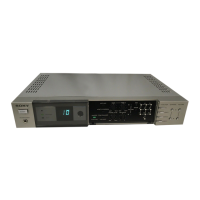
Section 6 Electrical Parts List

Related product manuals