SECTION 3
SAFETY RELATED ADJUSTMENTS
6 + MAX VOLTAGE CONFIRMATION CONFIRMATION FOR HOLD-DOWN CIRCUIT
When replacing the components (marked with 0 on the
schematic diagram), perform the adjustment as follows :
When replacing the components (marked with a on the
schematic diagram), perform the following confirmation.
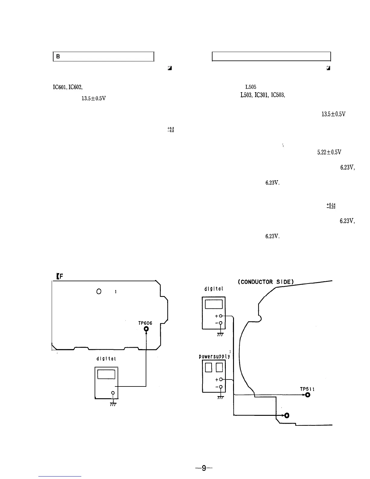
IC601,
IC602,
R601, R602, R623, R624, R625
1.
Supply 13.5f0.5V DC to the DC IN jack.
2.
Receive the monoscope signals.
3.
Set the PICTURE and BRIGHTNESS control to center
position.
4.
Confirm the voltage of TP606 is within 24.0
?!:a
V DC.
5.
Adjust the above voltage with RV601 when the voltage is
not in the value.
TP502 (FBT),
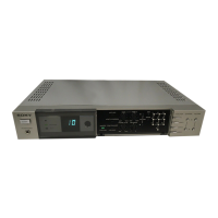
L505
(DY : Supplied with Picture tube.), C555,
C571, C556, L503, IC301, IC503, D503, D507, R562, R563, R573,
R574, C557, R571, R572, Q506, R575, C365, R361, R360
1.
Turn the POWER switch ON, and supply 13.5+0.5V DC
to the DC IN jack.
2.
Receive the monoscope signals.
3.
Set the PICTURE and BRIGHTNESS control to center
position.
;
4.
Confirm the voltage of TP512 is within 5.22*0.5V DC.
5.
Supply DC voltage from the regulated-dc power supply to
TP512 and gradually increase the voltage towards 6.23V,
then confirm the hold-down (raster will disappear) before
the voltage reach
6.23V.
6. Disconnect the DC power Turn the POWER switch OFF,
then turn the POWER switch ON again.
7.
Confirm the voltage of TP511 is within 5.66
Z%
V DC.
8.
Supply DC voltage from the regulated-dc power supply to
TP511 and gradually increase the voltage towards
6.23V,
then confirm the hold-down (raster will disappear) before
the voltage reach
6.23V.
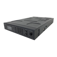
Adjustment Location :
[F
BOARD] (CONDUCTOR SIDE)
,
0
RV60
I
dlgltal
voltmeter
0
to
P
[D BOARD]
dlgl tal
voltmeter
regulated-dc
powersupply
TP511TP511
TP512TP512
-0-0
-9-