EasyManua.ls Logo

Sony Handycam DCR-PC115 User Manual

Sony Handycam DCR-PC115
207 pages
To Next Page IconTo Next Page
Page #1 background imageLoading...
Page #1 background image
Video camera
recorder
System
Video recording system
2 rotary heads
Helical scanning system
Audio recording system
Rotary heads, PCM system
Quantization: 12 bits (Fs 32 kHz,
stereo 1, stereo 2), 16 bits
(Fs 48 kHz, stereo)
Video signal
PAL colour, CCIR standards
NTSC color, EIA standards
DCR-PC115/PC120BT:
DCR-PC115E/PC120E:
Usable cassette
Mini DV cassette with the
mark printed
Tape speed
SP: Approx. 18.81 mm/s
LP: Approx. 12.56 mm/s
Recording/playback time (using
cassette DVM60)
SP: 1 hour
LP: 1.5 hours
Fastforward/rewind time (using
cassette DVM60)
When using the battery pack:
Approx. 2 min. and 30 seconds
When using the AC power adaptor:
Approx. 1 min. and 45 seconds
Viewfinder
Electric viewfinder (colour)
Image device
4.5 mm (1/4 type) CCD (Charge
Coupled Device)
Approx. 1 550 000 pixels
(Effective (moving): 970 000 pixels)
(Effective (still): 1 390 000 pixels)
Lens
Carl Zeiss Vario-Sonnar T*
Combined power zoom lens
Filter diameter: 37 mm (1 1/2 in)
10× (Optical), 120× (Digital)
Focal length
4.2 – 42 mm (3/16 – 1 11/16 in.)
When converted to a 35 mm still
camera
Camera mode:
48 – 480 mm (1 15/16 – 19 in.)
Memory mode:
40 – 400 mm (1 5/8 – 15 3/4 in.)
Colour temperature
Auto, HOLD (Hold),
Indoor
(3 200 K),
Outdoor (5 800 K)
Minimum illumination
7 lx (lux) (F 1.8)
0 lx (lux) (in the NightShot mode)*
* Objects unable to be seen due to
the dark can be shot with infrared
lighting.
Input/Output connectors
S video input/output
4-pin mini DIN
Luminance signal: 1 Vp-p,
75 (ohms), unbalanced
Chrominance signal: 0.3 Vp-p,
DCR-PC115/PC120BT:
DCR-PC115E/PC120E:
75 (ohms), unbalanced
Chrominance signal: 0.286 Vp-p,
75 (ohms), unbalanced
Audio/Video input/output
AV MINI JACK, 1 Vp-p,
75 (ohms), unbalanced, sync
negative
327 mV, (at output impedance
more than 47 k (kilohms))
Output impedance with less than
2.2 k (kilohms)/Stereo minijack
(ø 3.5 mm)
Input impedance more than
47 k (kilohms)
DV input/output
4-pin connector
Headphone jack
Stereo minijack (ø 3.5 mm)
LANC jack
Stereo mini-minijack (ø 2.5 mm)
USB jack
mini-B
MIC jack
Minijack, 0.388 mV low impedance
with 2.5 to 3.0 V DC, output
impedance 6.8 k (kilohms) (ø 3.5
mm)
Stereo type
SERVICE MANUALSERVICE MANUAL
DIGITAL VIDEO CAMERA RECORDER
SPECIFICATIONS
For MECHANISM ADJUSTMENTS, refer to the
“DV MECHANICAL ADJUSTMENT MANUAL
J MECHANISM (9-929-807-11).
— Continued on next page —
Level 2
On the VC-270 board
This service manual provides the information that is premised the
circuit board replacement service and not intended repair inside the
VC-270 board.
Therefore, schematic diagram, printed wiring board, waveforms, parts
location and electrical parts list of the VC-270 board are not shown.
The following pages are not shown.
Printed wiring board ......................... Pages 4-19 to 4-22
Schematic diagram .......................... Pages 4-23 to 4-58
Waveforms and parts location ......... Pages 4-92 to 4-94
Electrical parts list ............................ Pages 6-14 to 6-25
DCR-PC115/PC115E/
PC120BT/PC120E
RMT-811
Photo : DCR-PC120E
RMT-811
Canadian Model
DCR-PC120BT
AEP Model
DCR-PC115E/PC120E
UK Model
Australian Model
DCR-PC120E
E Model
DCR-PC115/PC115E/PC120E
Hong Kong Model
DCR-PC115/PC120E
Tourist Model
DCR-PC115/PC115E
Chinese Model
DCR-PC115E
Korea Model
DCR-PC115
NTSC model : DCR-PC115/PC120BT
PAL model : DCR-PC115E/PC120E
J MECHANISM
Ver 1.0 2001. 09

Table of Contents

Question and Answer IconNeed help?

Do you have a question about the Sony Handycam DCR-PC115 and is the answer not in the manual?

Sony Handycam DCR-PC115 Specifications

General IconGeneral
Recording MediaMiniDV
Effective Pixels1.07 megapixels
ViewfinderColor
Image StabilizationElectronic
MicrophoneStereo
Image Sensor1/4 inch CCD
LCD Screen2.5 inch
InterfaceIEEE 1394 (FireWire), USB
TypeDigital Camcorder

Summary

Service Manual Overview

Specifications

Detailed technical specifications for the video camera recorder's components and features.

Supplied Accessories

List of accessories provided with the camcorder, including part numbers and descriptions.

Safety Check-out Procedures

Unleaded Solder Information

Information and characteristics of unleaded solder used in some circuit boards.

Service Notes for Repair

Power Supply During Repairs

Methods to prevent power shutoff during repairs and safe handling of power supply.

Discharging Flash Power Supply Capacitor

Procedures for safely discharging the high-voltage capacitor in the flash unit to prevent electric shock.

Self-Diagnosis Functions

Self-Diagnosis Display and Service Mode

Explanation of self-diagnosis display, service mode access, and switching through past error codes.

Self-Diagnosis Code Table

Comprehensive table mapping self-diagnosis codes to symptoms and corresponding corrections.

Getting Started Guide

Main Features and Quick Start

Overview of primary functions, initial setup, cassette insertion, and basic recording procedures.

Recording Basics

Recording a Picture

Instructions on how to record still or moving images, including basic camera operations and settings.

Checking the Recording

END SEARCH / EDITSEARCH / Rec Review

Using specific buttons to check recorded scenes and ensure smooth transitions between recorded and new scenes.

Playback Basics

Playing Back a Tape

Procedures for monitoring playback pictures on the screen or viewfinder and using playback controls.

Advanced Recording Operations

Tape Photo Recording

Instructions for recording still images like photographs onto a tape, including settings and notes.

Manual White Balance Adjustment

Manual adjustment of white balance for accurate color reproduction, covering different modes and precautions.

SECTION 2 DISASSEMBLY

LCD Cabinet (R) Assembly Disassembly

Step-by-step procedure for disassembling the LCD cabinet (R) assembly, including screw and claw references.

Cabinet (L) Section Disassembly

Detailed instructions for disassembling the cabinet (L) section, including precautions for installation.

SECTION 3 BLOCK DIAGRAMS

Overall Block Diagram (1/4)

A high-level overview of the camcorder's internal circuitry and component interconnections.

SECTION 4 PRINTED WIRING BOARDS AND SCHEMATIC DIAGRAMS

Frame Schematic Diagram (1/3)

Printed wiring board layout for the camera's front frame, showing component placement and connector details.

SECTION 5 ADJUSTMENTS

Camera Section Adjustments

Procedures for adjusting various camera functions, including color reproduction, white balance, and exposure.

Mechanism Section Adjustment

Steps for adjusting the camcorder's mechanism, such as tape path and servo systems.

SECTION 6 REPAIR PARTS LIST

Exploded Views

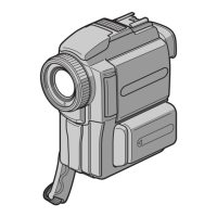
Visual breakdown of the camcorder's major assemblies, with numbered parts for identification.

Cabinet (L) Section Parts List

Detailed parts list and exploded view for the cabinet (L) section, including screws and internal components.

TROUBLESHOOTING

Types of Trouble and Their Solutions

Comprehensive guide to common problems, their causes, and corrective actions for recording and playback modes.

WARNING INDICATORS AND MESSAGES

Warning Indicators

List of warning indicators and messages that may appear on the screen, with explanations and corrective actions.

Related product manuals