EasyManua.ls Logo

Sony HBD-DZ170 User Manual

Sony HBD-DZ170
92 pages
To Next Page IconTo Next Page
Page #1 background imageLoading...
Page #1 background image
SERVICE MANUAL
Sony Corporation
Audio&Video Business Group
Published by Sony Techno Create Corporation
HBD-DZ170/DZ171/DZ175/DZ310/
DZ510/DZ610/DZ810
SPECIFICATIONS
DVD RECEIVER
9-889-740-01
2010A04-1
©
2010.01
US Model
HBD-DZ170/DZ171/DZ175
Canadian Model
HBD-DZ175
E Model
HBD-DZ310/DZ510/DZ610/DZ810
Ver. 1.0 2010.01
• HBD-DZ170/DZ171/DZ175/DZ310/DZ510/DZ610/DZ810
are the ampli er, DVD/CD and tuner section in DAV-DZ170/
DZ171/DZ175/DZ310/DZ510/DZ610/DZ810.
Model Name Using Similar Mechanism HCD-FZ900KW/FZ900M
Mechanism Type CDM85MB-DVBU102
Optical Pick-up Name KHM-313CAA
This system incorporates with Dolby* Digital and Dolby Pro Logic (II)
adaptive matrix surround decoder and the DTS** Digital Surround System.
* Manufactured under license from Dolby Laboratories.
Dolby, Pro Logic, and the double-D symbol are trademarks of Dolby
Laboratories.
** Manufactured under license under U.S. Patent #’s:
5,451,942; 5,956,674; 5,974,380; 5,978,762; 6,487,535 & other U.S. and
worldwide patents issued & pending. DTS and DTS Digital Surround
are registered trademarks and the DTS logos and Symbol are trademarks
of DTS, Inc. © 1996-2008 DTS, Inc. All Rights Reserved.
AUDIO POWER SPECIFICATIONS
for the U.S. model
POWER OUTPUT AND TOTAL HARMONIC
DISTORTION:
(FTC)
Front L + Front R With 3 ohms loads, both
channels driven, from 180
- 20,000 Hz; rated 84 watts
per channel minimum
RMS power, with no more
than 1% total harmonic
distortion from 250 milli
watts to rated output.
Ampli er Section
(DAV-DZ170/DAV-DZ171/DAV-DZ175)
U.S. models:
POWER OUTPUT (reference):
Front L/Front R/Center/
Surround L/Surround R:
167 watts (per channel at 3
ohms, 1 kHz)
Subwoofer: 165 watts (at 3
ohms, 80 Hz)
Other models:
POWER OUTPUT (rated):
Front L + Front R 108 W + 108 W (at 3 ohms,
1 kHz, 1% THD)
POWER OUTPUT (reference):
Front L/Front R/Center/
Surround L/Surround R:
167 watts (per channel at 3
ohms, 1 kHz)
Subwoofer: 165 watts (at 3
ohms, 80 Hz)
Inputs (Analog)
TV/CABLE (AUDIO IN) Sensitivity: 450/250 mV
AUDIO IN Sensitivity: 250/125 mV
Inputs (Digital)
TV/CABLE (COAXIAL IN/OPTICAL IN)
Impedance: 75 ohms/-
Input Stream: Dolby
Digital 5.1ch/DTS 5.1ch/
Linear PCM 2ch
(Sampling Frequency: less
than 48 kHz)
Ampli er Section
(DAV-DZ310/DAV-DZ510/DAV-DZ610/
DAV-DZ810)
DAV-DZ310
POWER OUTPUT (rated):
Front L + Front R 108 W + 108 W (at 3 ohms,
1 kHz, 1% THD)
POWER OUTPUT (reference):
Front L/Front R/Center/
Surround L/Surround R:
142 watts (per channel at 3
ohms, 1 kHz)
Subwoofer: 140 watts (at 3
ohms, 80 Hz)
DAV-DZ510/DAV-DZ610/DAV-DZ810
POWER OUTPUT (rated):
Front L + Front R 108 W + 108 W (at 3 ohms,
1 kHz, 1% THD)
POWER OUTPUT (reference):
Front L/Front R/Center/
Surround L/Surround R:
167 watts (per channel at 3
ohms, 1 kHz)
Subwoofer: 165 watts (at 3
ohms, 80 Hz)
Inputs (Analog)
TV (AUDIO IN) Sensitivity: 450/250 mV
AUDIO IN Sensitivity: 250/125 mV
MIC Sensitivity: 1 mV
Inputs (Digital)
DAV-DZ310:
TV (Audio Return Channel)
Input Stream: Dolby
Digital 5.1ch/DTS 5.1ch/
Linear PCM 2ch
(Sampling Frequency: less
than 48 kHz)
DAV-DZ510/DAV-DZ610/DAV-DZ810:
TV (Audio Return Channel/OPTICAL IN)
Input Stream: Dolby
Digital 5.1ch/DTS 5.1ch/
Linear PCM 2ch
(Sampling Frequency: less
than 48 kHz)
– Continued on next page –
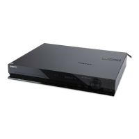
Photo: HBD-DZ170

Table of Contents

Question and Answer IconNeed help?

Do you have a question about the Sony HBD-DZ170 and is the answer not in the manual?

Sony HBD-DZ170 Specifications

General IconGeneral
TypeHome Theater System
Surround System Class5.1 channel
Channels5.1
Power Output1000W
Blu-ray PlaybackNo
DVD PlaybackYes
HDMI Inputs1
HDMI Output1
USB PortYes
BluetoothNo
Audio Formats SupportedDolby Digital, DTS
DVD playerYes
TunerFM
Supported Disc FormatsDVD, CD
Dimensions430 x 200 x 290 mm

Summary

Service Safety and Repair Notes

US Model Safety Checks

Safety checks required for US models, including AC leakage testing.

Diagnostic Features and Model Information

Self-Diagnosis Function Guide

Guide to interpreting self-diagnosis codes and display messages.

Servicing Notes and Precautions

Optical Pick-up and Laser Handling

Precautions for handling optical pick-up and laser diodes.

Safety and Assembly Guidance

Capacitor Discharge Procedure

Procedure for discharging capacitors to prevent electric shock.

Disassembly Procedures Overview

Case and Panel Disassembly

Overview of initial disassembly steps for case and panels.

Disassembly: Case Removal

Disassembly: Main Board Removal

Disassembly: I/O and Power Boards

I/O Board Removal Steps

Procedure for removing the I/O board.

Power Board Removal Steps

Procedure for removing the power board.

Disassembly: Mechanism and Tray

DVD Mechanism Deck Removal

Procedure for removing the DVD mechanism deck assembly.

Disassembly: Base Unit and Pick-up

Optical Pick-up Replacement Steps

Procedure for removing and replacing the optical pick-up.

Test Mode Procedures

Cold Reset and Panel Test Modes

Procedures for cold reset and panel test modes.

Specialized Test Modes and Settings

Acoustic Calibration Test Mode

Procedure for automatic acoustic calibration using calibration mic.

Protection Factor Identification Tests

Tests for identifying protection factors like SD, DC, and TSD.

IOP Measurement Procedures

General Description and Test Mode Entry

Overview of IOP measurement and how to enter test mode.

Executing IOP Measurement Steps

Detailed steps for executing the IOP measurement procedure.

Emergency History and Data Clearing

Checking and Clearing Emergency History

Procedure for checking and clearing the emergency history log.

Electrical Adjustments

DVD Section IOP Measurement

Procedure for IOP measurement in the DVD section.

Block Diagram: RF Section

Block Diagram: Video Section

Block Diagram: Audio Section

Block Diagram: Amplifier Section

Block Diagram: Power Supply Section

Printed Wiring Board: MAIN Section (1/2)

Printed Wiring Board: MAIN Section (2/2)

Schematic Diagram: MAIN Section (1/9)

Schematic Diagram: MAIN Section (2/9)

Schematic Diagram: MAIN Section (3/9)

Schematic Diagram: MAIN Section (4/9)

Schematic Diagram: MAIN Section (5/9)

Schematic Diagram: MAIN Section (6/9)

Schematic Diagram: MAIN Section (7/9)

Schematic Diagram: MAIN Section (8/9)

Schematic Diagram: MAIN Section (9/9)

Printed Wiring Board: I/O Section

Schematic Diagram: I/O Section

Printed Wiring Boards: Jack, Key-SW, P-SW

Schematic Diagram: Jack Section

Schematic Diagram: Key-SW and P-SW Sections

Printed Wiring Boards: Speaker, USB, MS-203

Schematic Diagram: Speaker and USB Sections

Printed Wiring Boards: FL and Encoder Sections

Schematic Diagram: FL Section

Schematic Diagram: Encoder Section

Printed Wiring Board: S-AIR CON Section

Schematic Diagram: S-AIR CON Section

Printed Wiring Board: Power Section

Schematic Diagram: Power Section

IC Block Diagrams and Pin Functions

IC Pin Function Descriptions: MAIN Board (IC1101)

IC Pin Function Descriptions: MAIN Board (IC1101 - cont.)

IC Pin Functions: MAIN Board (IC503)

IC Pin Functions: MAIN Board (IC503 - cont.)

Exploded View: DVD Mechanism Deck

Electrical Parts List

Parts List: FL and I/O Board Components

Parts List: I/O and Jack Board Components

Parts List: Jack, Key-SW Board Components

Parts List: Main Board Capacitors (Part 1)

Parts List: Main Board Capacitors (Part 2)

Parts List: Main Board Capacitors (Part 3)

Parts List: Main Board Diodes, Connectors, ICs

Parts List: Main Board ICs, Jacks, Coils, Transistors

Parts List: Main Board Resistors (Part 1)

Parts List: Main Board Resistors (Part 2)

Parts List: Main Board Resistors (Part 3)

Parts List: Main Board Capacitors (Part 4)

Parts List: Power Board Components

Parts List: Power and S-AIR CON Components

Parts List: Speaker and USB Components

Related product manuals