HBD-E190/E290/E490/E690
4
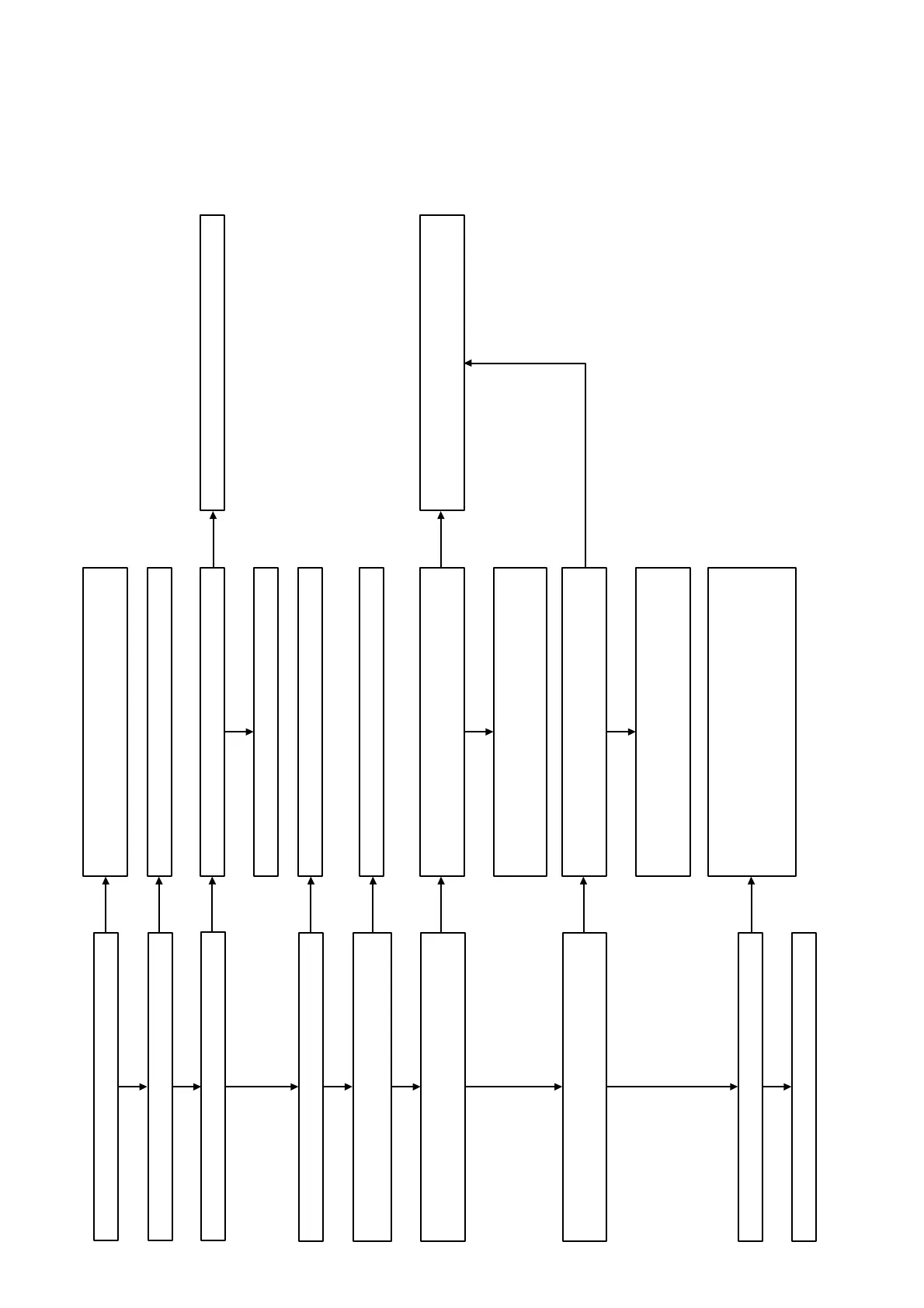
Video Check Flow
Check that the drive is operating normally.
Check that each power supply is supplied.
Yes
Yes
Yes
Yes
Yes
Yes
Yes
Yes
Yes
Yes
Check that VIDEO OUT is outputted normally.
Check that only the digital output (HDMI) is affected.
Check that the input voltage of the following pin is 6 V.
MB148 board IC705 pin 5 (VIN)
Check that the output voltage of the following pin is 5 V.
MB148 board IC705 pin 4 (VOUT)
Yes
Check that the output voltage of the following pin is 3.3V.
MB148 board IC704 pin4 (VOUT)
Check that there are no abnormalities in CN701.
Perform other analyses.
Check the settings on the menu screen.
Refer to the “1. Power Check Flow” on page 2.
Check that the input voltage of the following pin is 3.3V.
MB148 board IC705 pin1 (CONT)
Check that there are no abnormalities in J6401.
Exchange the complete MB148 board.
Check the solder of J6401.
Refer to the “1. Power Check Flow” on page 2 to check
on power control signal for PCONT_3
Refer to the “2-1. Flow of drive section check” on
page 7 on original service manual.
Exchange the IC705.
Part No. 6-705-337-01
Description IC TK11150CSCL-G
Check that the input voltage of the following pin is 3.3V.
MB148 board IC704 pin1 (CONT)
Refer to the “1. Power Check Flow” on page 2.
Exchange the IC704.
Part No. 6-702-302-01
Description IC TK11133CSCL-G
Part No. 1-821-398-41
Description HDMI CONNECTOR (HDMI OUT ARC)
Exchange the CN701
Note: When CN701 is exchanged, be careful of the
quality of soldering enough.
No
No
No
No
No
No
No
No
No
No
No