— 10 —
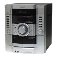
2. Turn the adjustment screw and check output peaks. If the peaks
do not match for L-CH and R-CH, turn the adjustment screw so
that outputs match within 2 dB of peak.
3. Mode: Playback
good
R
L-CH
peak
R-CH
peak
output
level
screw
position
within 2dB
L-CH
peak
R-CH
peak
screw
position
test tape
P-4-A100
(10kHz, –10dB)
SPEAKER
terminal
(L-CH)
set
L
oscilloscope
SPEAKER
terminal
(R-CH)
Waveform of oscilloscope
wrong
in phase
45˚
90˚
135˚ 180˚
within
2dB
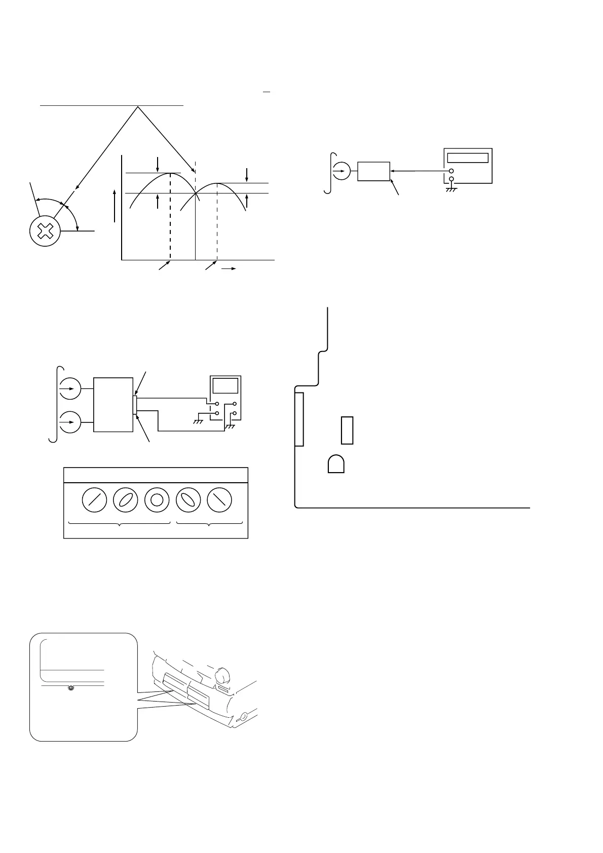
4. After the adjustments, apply suitable locking compound to the
parts adjusted.
Adjustment Location:
Adjustment screws
REC/PB head (deck A)
or PB head (deck B)
test tape
WS-48B
(3kHz, 0dB)
set
SPEAKER
terminal
frequency counter
+
Tape Speed Adjustment (Deck A)
Procedure:
1. Mode: Playback
–
2. Adjust the SFR201 so that the frequency counter reads 3,000
Hz ± 90 Hz.
Adjustment Location
[MAIN BOARD] — Component side —
CN205
CN301
SFR201
Tape Speed
Sample Value of Wow and flutter
W. RMS (JIS) within 0.3%
(test tape: WS-48B)