— 12 —
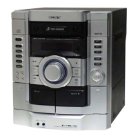
FM Tuned Level Adjustment
FM Tracking Adjustment
(EXCEPT AEP, UK models)
FM RF SSG
oscilloscope
FM ANTENNA terminal (JK101)
SPEAKER terminal
set
Carrier frequency : 90 MHz, 106 MHz
Modulation : AUDIO 1kHz, 75kHz deviation (100%)
Output level : 20 dB (at 75
Ω
open)
+
–
Procedure:
1. Tune the set to 90 MHz.
2. Adjust L102 so that when the waveform on the oscilloscope is
maximum, no noise appears.
3. Tune the set to 106 MHz.
4. Adjust TC101 so that when the waveform on the oscilloscope is
maximum, no noise appears.
• Repeat the procedures in each adjustment several times, and the
tracking adjustment should be finally done by the trimmer
capacitors.
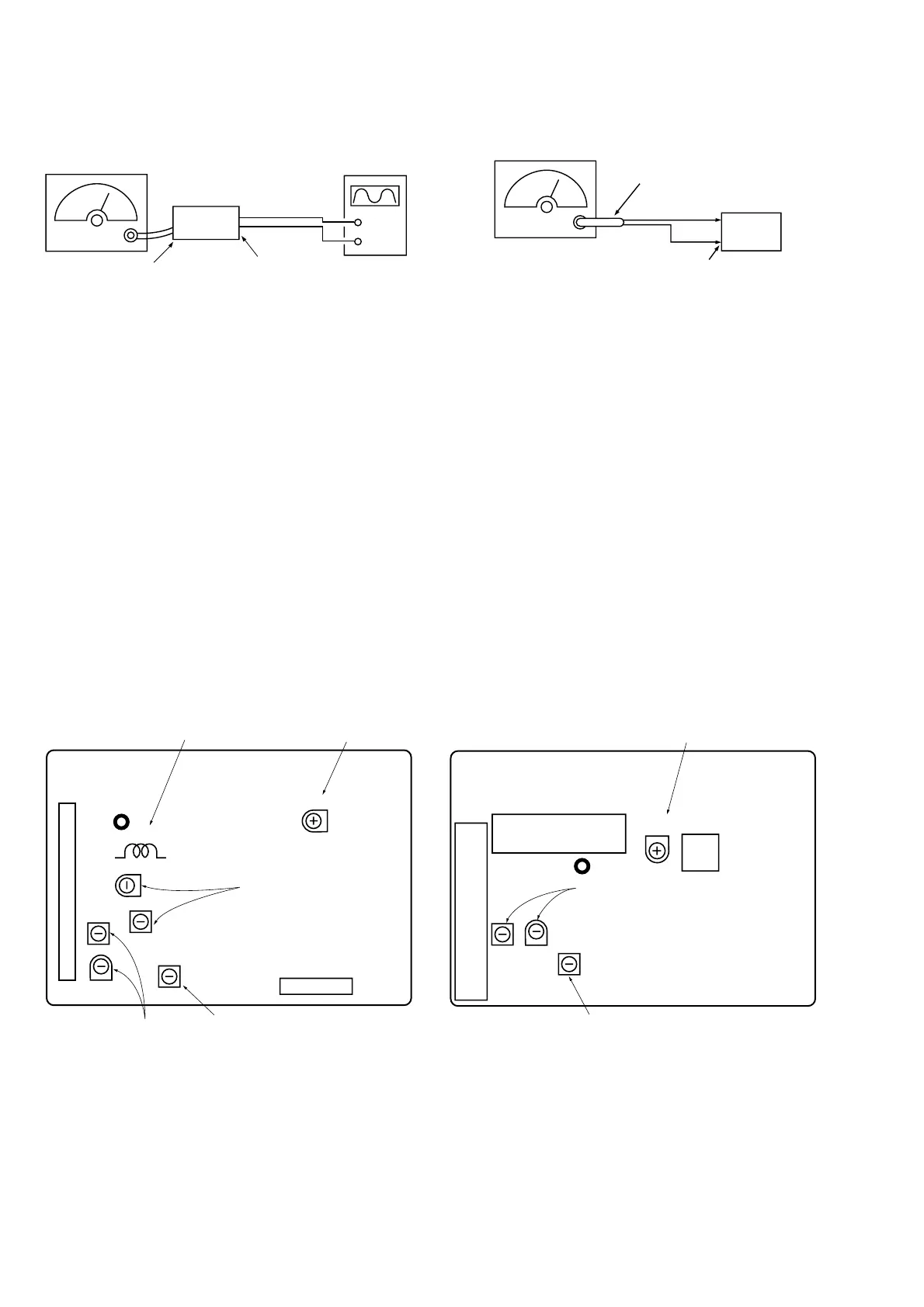
Adjustment Location: TUNER board
Adjustment Location
EXCEPT AEP, UK models
[TUNER BOARD] — Component side —
AEP, UK models
[TUNER BOARD] — Component side —
TP2 (VT)
FM Tuning Voltage
FM Tuned Level
JK101
L103
TC101
L104
L102
FM Tracking
L105
TC102
AM Tracking
AM Tuning Voltage
CN101
Carrier frequency : 98 MHz
Modulation : AUDIO 1 kHz, 75 kHz
deviation (100%)
Output level : 28 dB (at 75
Ω
open)
FM RF SSG
set
75
Ω
coaxial
FM ANTENNA terminal
(JK101)
Procedure:
1. Supply a 28 dB 98 MHz signal from the ANTENNA terminal.
2. Tune the set to 98 MHz.
3. Adjust SFR101 to the point (moment) when the TUNED indica-
tor will change from going off to going on.
Adjustment Location: TUNER board
U1
JK101
L104
TC102
L105
AM Tuning Voltage
SFR101
T101
FM Tuned Level
SFR101
AM Tracking
TP2 (VT)