Do you have a question about the Sony HCD-F150 and is the answer not in the manual?
Details the disassembly steps for the unit's case.
Explains how to disassemble the front panel.
Details the disassembly of the door assembly.
Describes the procedure for removing the back panel.
Explains the process of removing the main board.
Instructions for disassembling the CD mechanism deck.
Instructions for removing the optical pick-up.
Details the disassembly of the tape mechanism deck.
Resets memory and preset data.
Checks unit operations, versions, and performance.
Details mechanical adjustments for tape and CD mechanisms.
Covers deck section adjustments like torque and output peaks.
Details the procedure for adjusting the head azimuth.
Adjusts tape speed, bias, and playback level for deck B.
Adjusts playback level for Deck A and record level for Deck B.
Exploded view of the case section and its components.
Exploded view of the front panel and its components.
Exploded view of the first part of the mechanism deck.
Exploded view of the second part of the mechanism deck.
Exploded view of the optical pick-up section.
Exploded view of the tape mechanism deck section.
| Brand | Sony |
|---|---|
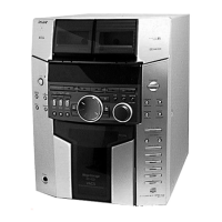
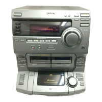
| Model | HCD-F150 |
| Category | Stereo System |
| Language | English |