EasyManua.ls Logo

Sony HCD-DR3 User Manual

Sony HCD-DR3
52 pages
To Next Page IconTo Next Page
Page #1 background imageLoading...
Page #1 background image
HCD-DR3/DR330/XB200
AEP Model
UK Model
HCD-XB200
E Model
HCD-DR3/DR330
Australian Model
HCD-DR3
SERVICE MANUAL
MICROFILM
Continued on next page
SPECIFICATIONS
COMPACT Hi-Fi STEREO SYSTEM
SPECIFICATIONS
HCD-DR3/DR330/XB200 is the tuner, deck,
CD and amplifier section in LBT-DR3/
DR330/XB200.
Model Name Using Similar Mechanism HCD-G2500
Base Unit Type
KSM-213ECM/C2NP
Optical Pick-up Type KSS-213E/C2N
Model Name Using Similar Mechanism NEW
Tape Transport Mechanism Type CWL-44-RR
CD
SECTION
TAPE
DECK
SECTION
Manufactured under license from Dolby Laboratories
Licensing Corporation.
“DOLBY” and the double-D symbol a are trademarks
of Dolby Laboratories Licensing Corporation.
Amplifier section
(LBT-XB200)
DIN power output (Rated) 70W + 70W
(6 at 1 kHz DIN)
Continuous RMS power output (Reference)
80W + 80W
(6 at 1 kHz, 10%
THD)
Music power output (Reference)
140W + 140W
(6 at 1 kHz, 10%
THD)
(LBT-DR330/DR3)
The following measured at AC 110/220V, 60Hz ;
Continuous RMS power output (Reference)
85W + 85W
(6 at 1 kHz, 10%
THD)
DIN power output (Rated) 70W + 70W
(6 at 1 kHz, DIN)
The following measured at AC 120/240V, 60Hz ;
Continuous RMS power output (Reference)
100W + 100W
(6 at 1 kHz, 10%
THD)
DIN power output (Rated) 80W + 80W
(6 at 1 kHz, DIN)
Inputs
PHONO IN (phono jack):
sensitivity 3mV,
impedance 47 k
MD/VIDEO IN (phono jacks):
sensitivity 250mV,
impedance 47 k
Outputs
PHONOS (stereo phono jacks):
accepts headphones of 8
or more
MD/VIDEO OUT (phone jack):
voltage 250mV,
impedance 1 k
SPEAKER: accepts impedance of 6 to
16
CD player section
System Compact disc and digital
audio system
Laser Semiconductor laser
(λ = 780 nm)
Emission
duration: continuous
Laser output Max. 44.6µW*
*This output is the value
measured at a distance of
200 mm from the objective
lens surface on the Optical
Pock-up Block with 7 mm
aperture.
Wavelength 780 – 790 nm
Frequency response 20Hz – 20kHz (±0.5 dB)
Signal-to-noise retio More than 90 dB
Dynamic range More than 90 dB
DIGITAL OUT
(Square optical connector jack, rear panel)
Wavelength 600 nm
Output Level –18 dBm
Tape deck section
Recording system 4-track 2-channel stereo
Frequency response (DOLBY NR OFF)
60 – 13,000 Hz (±3 dB),
using a Sony TYPE I
cassette
Tuner section
FM stereo, FM/AM superheterodyne tuner
FM tunr section
Tuning range 87.5 – 108.0 MHz
(50 kHz step)
Question and Answer IconNeed help?

Do you have a question about the Sony HCD-DR3 and is the answer not in the manual?

Sony HCD-DR3 Specifications

General IconGeneral
TypeMini Hi-Fi System
Audio Channels2.0
CD PlayerYes
Remote ControlYes
Weight (main unit)5.5 kg
FunctionsCD
Tuner BandsFM
CD Changer3-Disc
Speakers2 Speakers

Summary

System Specifications

Amplifier Section Details

Provides detailed specifications for the amplifier section including power output and impedance.

CD Player Section Specifications

Details the CD player mechanism, laser type, and output characteristics.

Tape Deck Section Specifications

Lists the recording system and frequency response for the tape deck.

Tuner Section Specifications

Outlines the tuner section's capabilities for FM and AM reception.

Disassembly Procedures

Top Cover Removal

Step-by-step guide for removing the top cover of the unit.

Front Panel Assembly Disassembly

Instructions for detaching and removing the front panel assembly.

Main Section Disassembly

Procedure for disassembling the main internal section of the device.

CD Mechanism Deck Section

Details on how to access and remove the CD mechanism deck.

Cassette Doors Removal

Guidance on removing the cassette doors.

CD Chassis Assembly

Steps for disassembling the CD chassis assembly.

Base Unit Disassembly

Instructions for taking apart the base unit.

Turn Table Disassembly

Procedure for disassembling the turn table mechanism.

Mechanical Adjustments

Torque Measurement Guidelines

Details on torque measurements for tape drive mechanisms.

Electrical Adjustments

Deck Section Electrical Adjustments

Procedures for adjusting the deck section, including azimuth and tape speed.

Tuner Section Electrical Adjustments

Steps for tuning voltage, tracking, and FM level adjustments.

Diagrams and Schematics

Circuit Boards Location Overview

Identifies the location of various circuit boards within the unit.

Block Diagrams

Provides high-level functional block diagrams of the system.

Printed Wiring Board Layouts

Illustrates the component placement on printed wiring boards.

Schematic Diagrams

Detailed circuit schematics for different sections of the device.

IC Pin Function Descriptions

Details the pin functions for key integrated circuits.

IC Block Diagrams

Functional block diagrams for integrated circuits used in the system.

Exploded Views of Components

Top Cover Section Exploded View

Diagram showing components of the top cover section.

CD Door Section Exploded View

Exploded view of the CD door mechanism and related parts.

Panel Section Exploded View

Diagram illustrating the various panels and their components.

Main Section Exploded View

Exploded view of the main internal components and boards.

CD Mechanism Section Exploded View

Detailed exploded view of the CD mechanism assembly.

Base Unit Section Exploded View

Exploded view of the base unit, including the KSM-213ECM.

Electrical Parts List

Capacitor Part Numbers

List of capacitors with part numbers, specifications, and remarks.

Resistor Part Numbers

List of resistors with part numbers, values, and remarks.

Diode Part Numbers

List of diodes with part numbers and specifications.

Integrated Circuit (IC) Part Numbers

List of integrated circuits with part numbers and descriptions.

Transistor Part Numbers

List of transistors with part numbers and specifications.
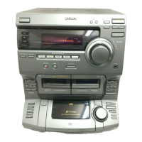
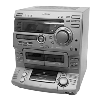
Related product manuals