SERVICE MANUAL
Sony Corporation
Personal Audio Division
Published by Sony Techno Create Corporation
US Model
Canadian Model
AEP Model
UK Model
E Model
Australian Model
DVD DECK RECEIVER
9-887-206-04
2006H16-1
© 2006.08
Ver. 1.3 2006.08
SPECIFICATIONS
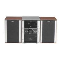
HCD-DX2D
HCD-DX2D is the Amplifier, DVD player, Tape
Deck and Tuner section in CMT-DX2D.
— Continued on next page —
This system incorporates Dolby
1)
Digital and DTS
2)
Digital
Surround System.
1)
Manufactured under license from Dolby Laboratories.
“Dolby”, “Pro Logic”, and the double-D symbol are trademarks
of Dolby Laboratories.
2)
Manufactured under license from Digital Theater Systems,
Inc. “DTS” and “DTS 2.0 + Digital Out” are trademarks of
Digital Theater Systems, Inc.
Amplifier section
AUDIO POWER SPECIFICATIONS
(USA model only)
POWER OUTPUT AND TOTAL HARMONIC
DISTORTION:
With 6 ohm loads, both channels driven, from
120 – 10,000 Hz: rated 50 watts per channel
minimum RMS power, with no more than 10%
total harmonic distortion from 250 milliwatts to
rated output.
North American model:
Continuous RMS power output (reference):
50 + 50 watts (6 ohms at
1kHz, 10% THD)
Total harmonic distortion less than 0.07% (6 ohms at
1kHz, 25 W)
European and Russian models:
DIN power output (rated): 40 + 40 watts (6 ohms at
1kHz, DIN)
Continuous RMS power output (reference):
50 + 50 watts (6 ohms at
1kHz, 10% THD)
Music power output (reference):
100 + 100 watts (6 ohms at
1kHz, 10% THD)
Inputs
TV IN (phono jacks): voltage 1 V,
impedance 47 kilohms
Outputs
VIDEO OUT (phono jack) (except for European
and Russian models): max. output level
1 Vp-p, unbalanced, Sync
negative, load impedance
75 ohms
LINE-TV (European and Russian models only):
max. output level 1 Vp-p,
unbalanced, Sync
negative, load impedance
75 ohms
COMPONENT VIDEO OUT:
Y: 1 Vp-p, 75 ohms
P
B
, P
R
: 0.7 Vp-p, 75 ohms
DIGITAL OUT (OPTICAL) (Square optical connector
jack, rear panel)
Wavelength 660 nm
PHONES (stereo mini jack):
accepts headphones of
8ohms or more
SPEAKER: accepts impedance of
6ohms
Disc player section
System Compact disc and digital
audio and video system
Laser Semiconductor laser
(DVD: λ=650 nm,
CD: λ=790 nm)
Emission duration:
continuous
Other models:
The following measured at AC 120 V, 240 V, 50/60 Hz
DIN power output (rated): 40 + 40 watts
(6 ohms at 1 kHz, DIN)
Continuous RMS power output (reference):
50 + 50 watts
(6 ohms at 1 kHz, 10%
THD)
Frequency response DVD (PCM 48 kHz):
2 Hz – 22 kHz (±1 dB)
CD: 2 Hz – 20 kHz (±1 dB)
Korean and Thai models:
The following measured at AC 220 V, 60 Hz
DIN power output (rated): 35 + 35 watts
(6 ohms at 1 kHz, DIN)
Continuous RMS power output (reference):
45 + 45 watts
(6 ohms at 1 kHz, 10%
THD)
DVD
Model Name Using Similar Mechanism NEW
Section
DVD Mechanism Type WXD
Optical Pick-up Name DM3451-A (SF-HD65F)
TAPE Model Name Using Similar Mechanism HCD-DV2D
Section Tape Transport Mechanism Type CMAL5Z220C
w
w
w
.
x
i
a
o
y
u
1
6
3
.
c
o
m
Q
Q
3
7
6
3
1
5
1
5
0
9
9
2
8
9
4
2
9
8
T
E
L
1
3
9
4
2
2
9
6
5
1
3
9
9
2
8
9
4
2
9
8
0
5
1
5
1
3
6
7
3
Q
Q
TEL 13942296513 QQ 376315150 892498299
TEL 13942296513 QQ 376315150 892498299
http://www.xiaoyu163.com
http://www.xiaoyu163.com