EasyManua.ls Logo

Sony HCD-DX2 User Manual

Sony HCD-DX2
72 pages
To Next Page IconTo Next Page
Page #1 background imageLoading...
Page #1 background image
SERVICE MANUAL
MINI HiFi COMPONENT SYSTEM
US Model
Canadian Model
AEP Model
UK Model
HCD-BX2
E Model
HCD-DX2/DX2B
Australian Model
HCD-DX2
SPECIFICATIONS
HCD-BX2/DX2/DX2B
HCD-BX2/DX2/DX2B is the Amplifier,
CD player, Tape Deck and Tuner
section in HMC-BX2/DX2/DX2B.
Photo: HCD-BX2
Dolby noise reduction manufactured under license
from Dolby Laboratories Licensing Corporation.
“DOLBY” and the double-D symbol ; are trade-
marks of Dolby Laboratories Licensing Corporation.
Model Name Using Similar Mechanism NEW
CD Mechanism Type EXL-M7
Optical Pick-up Name OPTIMA-7
Model Name Using Similar Mechanism HCD-GRX20
Tape Transport Mechanism Type CWL-44-FR
CD
Section
Tape deck
Section
AUDIO POWER SPECIFICATIONS:
(U.S.A. model only)
POWER OUTPUT AND TOTAL
HARMONIC DISTORTION:
with 6 ohm loads both channels driven, from
120 – 10,000 Hz; rated 60 watts per channel
minimum RMS power, with no more than
10% total harmonic distortion from
250 milliwatts to rated output.
Amplifier section
Canadian model:
Continuous RMS power output
50 + 50 watts
(6 ohms at 1 kHz,
10% THD)
European model:
DIN power output (Rated)
40 + 40 watts
(6 ohms at 1 kHz, DIN)
Continuous RMS power output (Reference)
50 + 50 watts
(6 ohms at 1 kHz,
10% THD)
Music power output (Reference)
100 + 100 watts
(6 ohms at 1 kHz,
10% THD)
Other models:
The following measured at AC 110, 220 V 60 Hz:
DIN power output (Rated)
45 + 45 watts
(6 ohms at 1 kHz, DIN)
Continuous RMS power output (Reference)
50 + 50 watts
(6 ohms at 1 kHz,
10% THD)
The following measured at AC 120, 240 V 60 Hz:
DIN power output (Rated)
50 + 50 watts
(6 ohms at 1 kHz, DIN)
Continuous RMS power output (Reference)
60 + 60 watts
(6 ohms at 1 kHz,
10% THD)
Inputs
MD IN: voltage 450 mV,
(phono jacks) impedance 47 kilohms
Outputs
PHONES: accepts headphones of
(stereo mini jack) 8 ohms or more
SPEAKER:
HCD-BX2: accepts impedance of 6 to
16 ohms
HCD-DX2: accepts impedance of 6 to
16 ohms
CD player section
System Compact disc and digital
audio system
Laser Semiconductor laser
(λ=780nm)
Emission duration:
continuous
Laser output Max. 44.6
µ
W*
*This output is the value
measured at a distance of
200 mm from the
objective lens surface on
the Optical Pick-up Block
with 7 mm aperture.
Wavelength 780 – 790 nm
Frequency response 20 Hz – 20 kHz (±0.5 dB)
Signal-to-noise ratio More than 90 dB
Dynamic range More than 90 dB
CD OPTICAL DIGITAL OUT
(Square optical connector jack, rear panel)
Wavelength 660 nm
Output Level –18 dBm
Tape player section
Recording system 4-track 2-channel stereo
Frequency response 40 13,000 Hz (±3 dB),
using Sony TYPE I
cassette
Tuner section
FM stereo, FM/AM superheterodyne tuner
FM tuner section
Tuning range 87.5 108.0 MHz
Antenna FM lead antenna
Antenna terminals 75 ohm unbalanced
Intermediate frequency 10.7 MHz
AM tuner section
Tuning range
Pan-American model: 530 1,710 kHz
(with the interval set at
10 kHz)
531 1,710 kHz
(with the interval set at
9 kHz)
European and Middle Eastern models:
531 1,602 kHz
(with the interval set at
9 kHz)
Other models: 531 1,602 kHz
(with the interval set at
9 kHz)
530 1,710 kHz
(with the interval set at
10 kHz)
Antenna AM loop antenna
Antenna terminals External antenna terminal
Intermediate frequency 450 kHz
Continued on next page
Ver 1.2 2001.07
9-929-070-13 Sony Corporation
2001G0500-1 Home Audio Company
C 2001.7 Shinagawa Tec Service Manual Production Group
Question and Answer IconNeed help?

Do you have a question about the Sony HCD-DX2 and is the answer not in the manual?

Sony HCD-DX2 Specifications

General IconGeneral
Audio OutputStereo
CD PlayerYes
Radio TunerYes
BluetoothNo
USB PlaybackNo
Speaker Configuration2.0
Cassette DeckYes
TypeMini System
Tuner BandsFM
Speakers2
FunctionsCD, Radio, Cassette
Dimensions (W x H x D)280 x 280 x 150 mm

Summary

SPECIFICATIONS

AUDIO POWER SPECIFICATIONS

Details output power and harmonic distortion for US models.

Amplifier section specifications

Specifies continuous RMS power output for Canadian and European models.

CD Player section specifications

Lists system type, laser specifications, wavelength, and output level.

Tape Player section specifications

Details recording system and frequency response for tape playback.

Tuner section specifications

Lists FM/AM tuner type and specifications.

SERVICING NOTES

Handling Optical Pick-up and Laser Diodes

Precautions for handling optical pick-up, laser diodes, and flexible circuit boards.

Component Replacement and Repair Guidelines

Advice on replacing chip components and repairing flexible circuit boards.

GENERAL INFORMATION

Location of Controls Overview

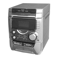
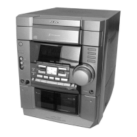
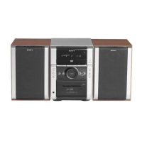
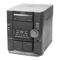
Identifies front and rear panel controls and connectors with numbered labels.

Setting the Device Clock

Instructions for setting the device's clock, essential for timer functions.

DISASSEMBLY PROCEDURES

CD Door Disassembly

Step-by-step visual guide for disassembling the CD door mechanism.

Front Panel Removal

Visual guide for removing the front panel section.

Mech Deck Disassembly

Visual guide for disassembling the mechanical deck unit.

Power Transformer and Rear Cover Removal

Visual guide for removing the power transformer and rear cover.

Board Removal Procedures

Visual guides for removing AMP, Main, CD Tray, Decode, Base Unit, and Cassette Lid.

DIAGRAMS AND SCHEMATICS

Notes on Printed Wiring Boards and Schematics

General notes on interpreting diagrams, including symbols and voltage conventions.

CD Section Schematics

Schematics for the CD section, including decode, switch, and motor boards.

Main Board Schematics

Schematics for the Main board, covering tuner, power supply, and tape circuits.

Panel Section Schematics

Schematics for the Panel section, covering front and sensor boards.

AMP Board Schematics and PWBs

Schematics and PWBs for the AMP board, including model variations.

WAVEFORM AND BLOCK DIAGRAMS

Decode Board Waveforms

Displays various waveforms measured on the DECODE board for different components.

Main Board IC Block Diagrams

Shows IC block diagrams for the MAIN board, illustrating circuit functions.

Front Board Waveforms

Displays waveforms measured on the FRONT board for various components.

EXPLODED VIEWS

Top Cabinet Section Exploded View

Exploded view of the top cabinet section, showing main assembly parts.

Front Panel Section Exploded View

Exploded view of the front panel section, detailing its components.

Bottom Cabinet Section Exploded View

Exploded view of the bottom cabinet section, showing internal components.

CD Mechanism Deck Exploded Views

Exploded views of CD mechanism deck sections 1, 2, and 3, showing parts.

ELECTRICAL PARTS LIST

Amplifier Section Parts List

Lists capacitors, connectors, diodes, ICs, terminals, and transistors for the amplifier section.

Decode Section Parts List

Lists resistors, coils, transistors, and diodes for the decode section.

Front Section Parts List

Lists capacitors, ICs, LEDs, transistors, resistors, and switches for the front section.

Main Section Parts List

Lists capacitors, transistors, resistors, variable resistors, and transformers for the main section.

Boards (Motor, Sensor, Socket, SW) Parts List

Lists connectors, capacitors, ICs, and switches for various boards.

SUPPLEMENT-1 REVISIONS

Printed Wiring Board - Panel Section Updates

Details updates for the printed wiring board of the panel section.

Schematic Diagram Updates and Notes

Covers updates to schematic diagrams for AMP/Power Supply and general diagram notes.

Schematic Diagram Changes (Tuner and CD Sections)

Illustrates schematic changes in the tuner and CD sections.

Printed Wiring Board Changes (AMP Board)

Shows printed wiring board changes on the AMP board for different models.

Printed Wiring Board Changes (AC SW Board)

Shows printed wiring board changes on the AC SW board and related components.

Printed Wiring Board Changes (AMP Board Variations)

Shows printed wiring board changes on the AMP board for E model and DX2 variations.

Exploded Views Updates (Front Panel and CD Doors)

Details changes in exploded views for front panels and CD doors.

Electrical Parts List Updates

Lists electrical parts updates for AC SW, AMP, and Fuse sections.

Front Board, Complete Part Number Changes

Lists changes in part numbers for front board assemblies and diodes.

Miscellaneous Part Number Changes

Lists changes in power cord and transformer part numbers.

Related product manuals