Do you have a question about the Sony HCD-DX8 and is the answer not in the manual?
Details amplifier input/output and power specifications.
Provides specifications for the CD player, including laser and frequency response.
Lists specifications for the tape deck mechanism.
General specifications including power requirements, mass, and voltage selector.
FM tuning range, antenna connection, and intermediate frequency.
AM tuning range, antenna connection, and intermediate frequency.
Notes on installing the panel board, including screw tightening and hot melt points.
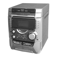
Identifies and describes the location of all front panel controls and indicators.
Procedure for removing the top case assembly during disassembly.
Steps for removing the loading panel assembly and CD mechanism deck.
Resets system data to initial conditions, clearing preset data.
Moves the CD pickup to a safe position for shipping after repair.
Resets the system while retaining preset data, simulating power cycling.
Allows free operation of the CD sled motor, useful for cleaning the pickup.
Switches the VACS system on or off, indicated by a message.
Allows changing the AM tuner step between 9 kHz and 10 kHz.
Checks software version, displays, LEDs, keyboard, and VACS status.
Checks operations of amplifier, tuner, CD, and tape sections.
Checks CD and tape deck operations repeatedly, simulating long-term use.
Allows switching between external FUNCTION inputs like VIDEO or MD.
Details torque measurements for various tape deck mechanisms like FWD, REV, and FF/REW.
Adjusting the record/playback head azimuth for optimal performance on both decks.
Adjusting tape speed for Deck B using test mode and frequency counter.
Adjusting playback signal levels for both decks to specified mV or dB values.
Adjusting recording bias for Deck B using a specific test mode and signal.
Adjusting recording level for Deck B to ensure proper signal output.
Adjusting FM tuned level by tuning the indicator and measuring voltage.
Verifying the symmetry and peak-to-peak level of the CD section's S-curve waveform.
Checking the clarity and signal level of the RF waveform in the CD section.
Checking the E-F balance of the CD player's 1-track jump waveform.
Verifying the RF PLL free-run frequency using a frequency counter.
Illustrates the physical placement of various circuit boards within the unit.
Shows the overall functional blocks and signal flow for the tuner/CD section.
Shows the component layout and connections on the BD board.
Detailed schematic of the BD board, showing component interconnections and voltages.
Component layout and connections for the main board.
Part 1 of the main board schematic, detailing FM/AM and PLL circuits.
Part 2 of the main board schematic, covering tape mechanism and amplifier circuits.
Part 3 of the main board schematic, including power supply and digital output circuits.
Component layout for the power amplifier board.
Schematic of the power amplifier board, showing output stages and protection circuits.
Component layout for the CD switch and panel boards.
Component layout for the leaf switch boards.
Schematic of the leaf switch boards, showing motor and sensor connections.
Component layout for motor, driver, and sensor boards.
Schematics for motor, driver, and sensor boards, detailing control logic.
Component layout for the transformer and related connections.
Schematic of the transformer section, showing power supply and voltage selector.
Details pin functions for IC401 SYSTEM CONTROLLER on the main board.
Block diagrams for IC101 and IC102 on the BD board, illustrating internal functions.
Exploded view of the outer cover and related components.
Exploded view of the front panel assembly and its parts.
Exploded view of the main chassis and associated wiring and boards.
Exploded view of the tape mechanism deck, showing all sub-components.
Exploded view of the CD mechanism deck, detailing its parts.
Exploded view of the base unit, including the optical pickup and BD board.
Parts list specifically for the BD board, including capacitors, connectors, ICs, and resistors.
Parts list for the CD switch board, including LEDs, transistors, resistors, and connectors.
Parts list for driver-related boards like Motor, Driver, and Sensor boards.
Parts list for various components on the main board, categorized by type.
Parts list for components on the panel board, including ICs, switches, and connectors.
Parts list for components on the power amp board, including transistors and resistors.
Parts list for the trans board, including fuses, resistors, switches, transformers, and miscellaneous items.
| Brand | Sony |
|---|---|
| Model | HCD-DX8 |
| Category | Stereo System |
| Language | English |