EasyManua.ls Logo

Sony HCD-DX20 User Manual

Sony HCD-DX20
60 pages
To Next Page IconTo Next Page
Page #1 background imageLoading...
Page #1 background image
HCD-DX20/RG30
AEP Model
UK Model
HCD-RG30
E Model
HCD-DX20
SERVICE MANUAL
MINI HIFI COMPONENT SYSTEM
Ver 1.3 2003.12
Sony Corporation
Home Audio Company
Published by Sony Engineering Corporation
9-873-858-14
2003L02-1
© 2003.12
HCD-DX20/RG30 is the tuner,
deck, CD and amplifier section in
MHC-DX20/RG30.
Model Name Using Similar Mechanism HCD-DX30/RG40
CD CD Mechanism Type CDM58B-K6BD38
Section Base Unit Name BU-K6BD38
Optical Pick-up Name KSM-213DAP
Tape deck
Model Name Using Similar Mechanism NEW
Section
— Continued on next page —
SPECIFICATIONS
Photo: HCD-DX20
SPEAKER: accepts impedance of 6 to 16 ohms
CD player section
System Compact disc and digital audio system
Laser Semiconductor laser (λ=780 nm)
Emission duration: continuous
Laser output Max. 44.6
µ
W*
* This output is the value measured at a distance
of 200 mm from the objective lens surface on
the Optical Pick-up Block with 7 mm aper-
ture.
Frequency response 2 Hz – 20 kHz (±0.5 dB)
Wavelength 780 – 790 nm
Signal-to-noise ratio More than 90 dB
Dynamic range More than 90 dB
CD OPTICAL DIGITAL OUT
(Square optical connector jack, rear panel)
Wavelength 660 nm
Output Level –18 dBm
Amplifier section
European models:
HCD-RG30:
DIN power output (rated) 50 + 50 watts (6 ohms at 1 kHz, DIN)
Continuous RMS power output (reference)
60 + 60 watts (6 ohms at 1 kHz, 10% THD)
Music power output (reference)
115 + 115 watts (6 ohms at 1 kHz, 10% THD)
Other models:
HCD-DX20:
The following measured at AC 120, 220, 240 V 50/60 Hz
DIN power output (rated) 50 + 50 watts (6 ohms at 1 kHz, DIN)
Continuous RMS power output (reference)
60 + 60 watts (6 ohms at 1 kHz, 10% THD)
Inputs
MD/VIDEO (AUDIO) IN (phono jacks):
voltage 450/250 mV, impedance 47 kilohms
GAME (AUDIO) IN (phono jacks):
voltage 450 mV, impedance 47 kilohms
MIC (mini jack): sensitivity 1 mV, impedance 10 kilohms
Outputs
PHONES (stereo mini jack):
accepts headphones of 8 ohms or more
Question and Answer IconNeed help?

Do you have a question about the Sony HCD-DX20 and is the answer not in the manual?

Sony HCD-DX20 Specifications

General IconGeneral
BrandSony
ModelHCD-DX20
CategoryStereo System
LanguageEnglish

Summary

Service Manual

Specifications

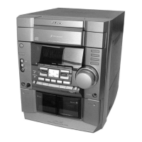
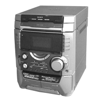
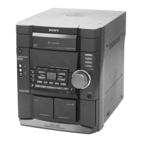
Detailed technical specifications for the HCD-DX20/RG30 system.

Amplifier Section

Technical details for the amplifier stage, including power output and model variations.

CD Player Section

Specifications related to the CD player system, laser, and performance metrics.

Handling and Safety Notes

Notes on Handling the Optical Pick-up Block

Precautions for handling the optical pick-up block to prevent damage.

Remote Control Operation

Remote Control Button Functions

List and description of functions for each button on the remote control.

Setting the System Time

Step-by-step guide on how to set the clock and timer functions.

Disassembly Procedures

Test Modes and Operations

MC Cold Reset Procedure

Procedure for clearing all stored data and resetting the system.

GC Test Mode Functions

Test mode for checking software version, FL tube, LEDs, and more.

MC Test Mode Operations

Mode to check operations of Amplifier, Tuner, CD, and Tape sections.

Aging Mode

Mode for operation check of CD and tape deck sections.

Electrical Adjustments and Checks

FM Tuned Level Adjustment

Procedure for adjusting the FM tuned signal level.

CD Section Adjustments

Notes and procedures for CD section adjustments, including S-Curve and RF Level checks.

Diagrams and Circuit Information

Block Diagrams - Tuner Section

Block diagram illustrating the signal flow in the tuner section.

Block Diagrams - Main Section

Block diagram illustrating the signal flow in the main section.

Schematic Diagram - BD Section

Schematic diagram detailing the BD section circuitry.

Schematic Diagram - Main Section (1/5)

Schematic detailing the first part of the main section circuitry.

Schematic Diagram - Main Section (2/5)

Schematic detailing the second part of the main section circuitry.

Schematic Diagram - Main Section (3/5)

Schematic detailing the third part of the main section circuitry.

Schematic Diagram - Main Section (4/5)

Schematic detailing the fourth part of the main section circuitry.

Schematic Diagram - Main Section (5/5)

Schematic detailing the fifth part of the main section circuitry.

IC Pin Function Description - Master Control

Pin function description for the Master Control IC (IC401).

IC Pin Function Description - Display Control

Pin function description for the Display Control IC (IC701).

IC Block Diagrams - BD Board

Block diagrams for ICs on the BD board (IC101, IC102, IC103).

IC Block Diagrams - Main Board

Block diagrams for ICs on the main board (IC102, IC103, IC201).

Exploded Views

Electrical Parts List

Related product manuals